
Exploring audio DACs in simulation – Part 3 – 2021-04-03
Having set up a simplistic testbench in Verilator, I want to be able to use it to evaluate several different DACs. The ones I will be testing are:
- The simple 1st-order Sigma Delta I included in my last post.
- A 2nd order DAC found on Github: https://github.com/hamsternz/second_order_sigma_delta_DAC/blob/master/second_order_dac.v – however, I’ve adapted this to halve the input volume by discarding the lowest bit, since second- (and higher) order 1-bit sigma delta DACs are unstable at the extremities of their input range – they require some headroom. Since the Amiga application only requires 15-bit input this is not a problem.
- A 3rd-order DAC found in Mark Watson’s Atari 800 repository. I’m not sure where it originally came from or what its copyright status is, since it’s not listed in Mark’s otherwise comprehensive list of which license applies to which files. The 3rd order DAC already attenuates the signal to maintain stability so I didn’t need to modify this one, except as detailed below.
- Finally, the simplest form of my hybrid DAC.
I also found a DAC written in VHDL at OpenCores, which has two variants – the description of these gave me the clue I finally needed to solve this puzzle!
In each case I edited the DACs so that they have a standard interface – “clk” and “reset_n”, a 16-bit wide input port, “d”, and a 1-bit output port, “q”.
I then make use of a blend of Makefiles and shell scripting to build the testbench against each DAC in turn, run the testbench and capture its output to a raw audio file, which I can then load in Audacity.
The Makefile uses the following construct to achieve this:
DACS = sigma_delta_dac_1storder hybrid_pwm_sd sigma_delta_dac_2ndorder sigma_delta_dac_3rdorder
TESTS = sine
all:
  for DAC in $(DACS); do \
    for TEST in $(TESTS); do \
      make $${TEST}_$${DAC}.raw TEST=$$TEST DAC=$$DAC; \
    done; \
  done
Note the backslashes, which mean that as far as the Makefile’s concerned everything after the first “for” is a single shell command. Without these, each line would be launched as a separate command, and the variables defined in the “for” constructs would be immediately lost.
So the makefile calls itself recursively with “sine_sigma_delta_dac_1storder.raw” as a target, then similarly for each of the other DACs in turn – and we can add new tests later, too.
So let’s load up the output files into Audacity and take a look. Each one in turn is imported as raw audio, with the format 16-bit little-endian, 1-channel.
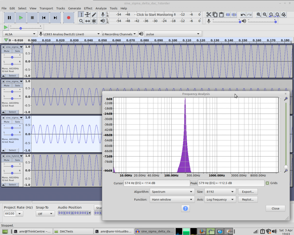
Frequency plots of the three standard DACs’ rendition of a sinewave are very similar to each other – while the hybrid DAC’s output is a little different:
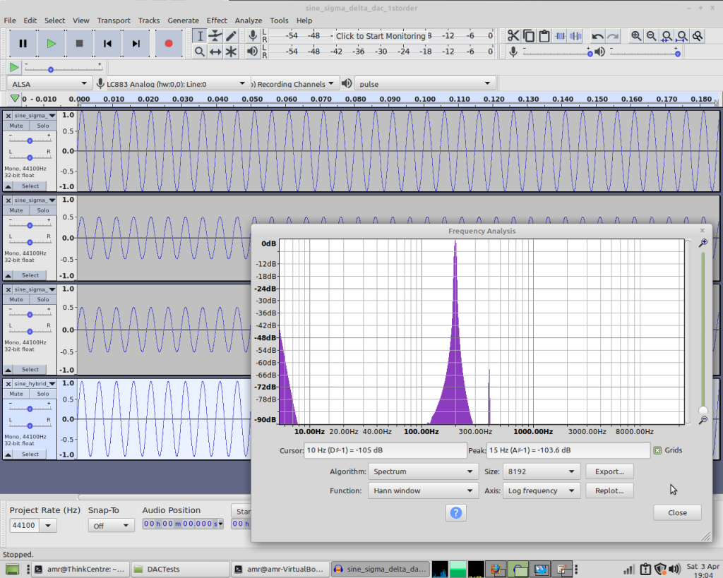
We have a slight DC offset, and also a bit of a second harmonic. So the hybrid DAC’s performing significantly worse than the others in this test – and I see similar results if I change the frequency of the sinewave.
However, we know the other DACs are struggling most when volume is low, so let’s create another test.
I copy the sine.cpp testbench to fadeout.cpp and make some changes to the code so that it ramps a sinewave’s volume down to zero. I add fadeout to the TESTS variable in the makefile and let it run. Again, the DACs’ results look very similar.
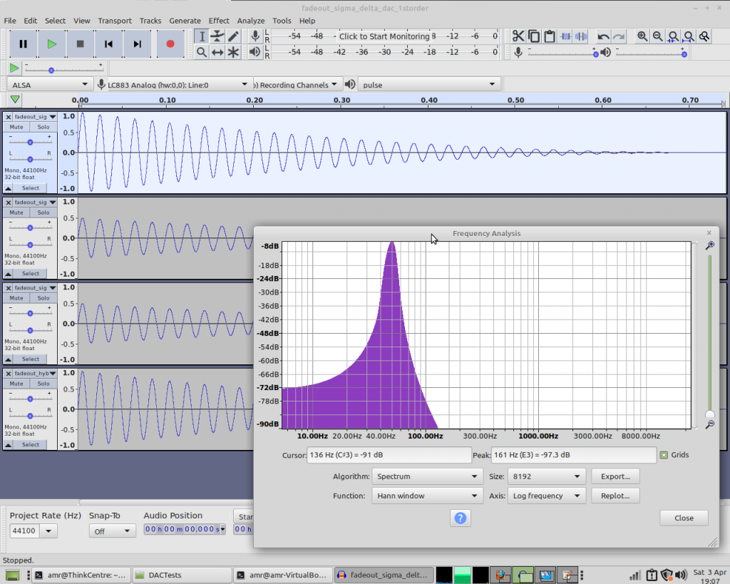
We have some low frequency noise, which I believe comes from the fact that the volume isn’t constant for each cycle of the sinewave, but there’s no real sign of misbehaviour here.
I can create a testbench which (rather slowly) reads a raw audio file, runs it through the DAC and writes it out again, and then listen to the results – and again I don’t see (or hear) any real sign of misbehaviour – so what gives? Did I dream the problems we were seeing a few years back?
So I built the MiST Minimig core using each of the DACs in turn and repeated some of the tests from back then. These recordings were made with the MiST connected to my PC’s line in, input gain set to maximum. Stardust Memories played using ProTracker 3.15 with the volume slider set one pixel above minimum – at normal comfortable listening levels this is just on the edge of being audible at 1/64th of its usual volume.
And the last few seconds of the fadeout at the end of the Gauntlet III title music. Again, this is recorded with input gain set to maximum, so this part of the tune is usually barely audible:
So… I didn’t dream it.
So how come the “regular” DACs are performing so much worse in real hardware than in simulation? I found the clue I needed in the description of the VHDL DAC on OpenCores that I mentioned earlier.
The simulation is happening in physics-experiment land, where there’s no friction, every variable starts out at a nice neat round number and edges are perfectly square.
The DACs are all built upon the same basic assumption, which is that thanks to the low-pass filtering of the reconstruction filter, the pulse trains represented by “00001111”, “00110011” and “01010101” will ultimately produce the same output. Is that actually true in practice, though? What happens if the amount of energy delivered to the filter on a rising edge differs from the amount removed on a falling edge?
Time to add another testbench – a copy of fadeout.cpp to asymmetric.cpp. We’ll change the output so that instead of simply multiplying the DAC’s q output by 65535, we’ll use a different value depending on whether it’s a rising or falling edge:
// Simulate asymmetric rising and falling edges...if(tb->q && s<32768) // Rising edge?s=0xdfff;else if(!tb->q && s>=32768) // Falling edge?s=0x5000;elses=(0xffff*tb->q);
These numbers are basically plucked out of thin air – they’re not based on any kind of measurement, and they’re probably quite extreme – but they’ll be enough to get an idea of how each DAC copes with asymmetric rising and falling edges.
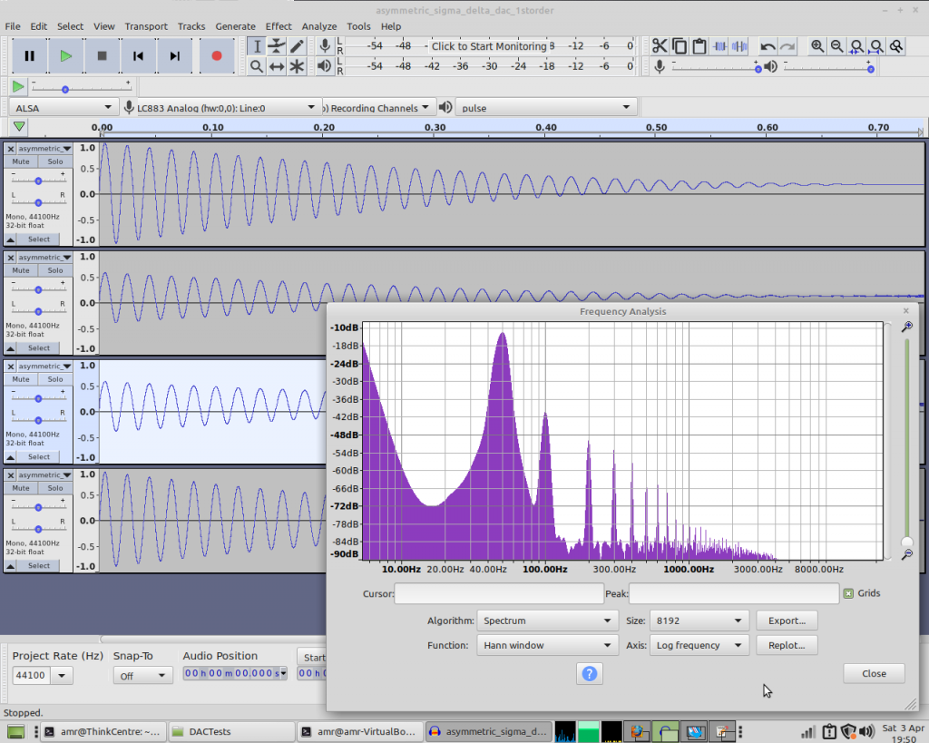
So let’s see how the 1st order DAC copes:
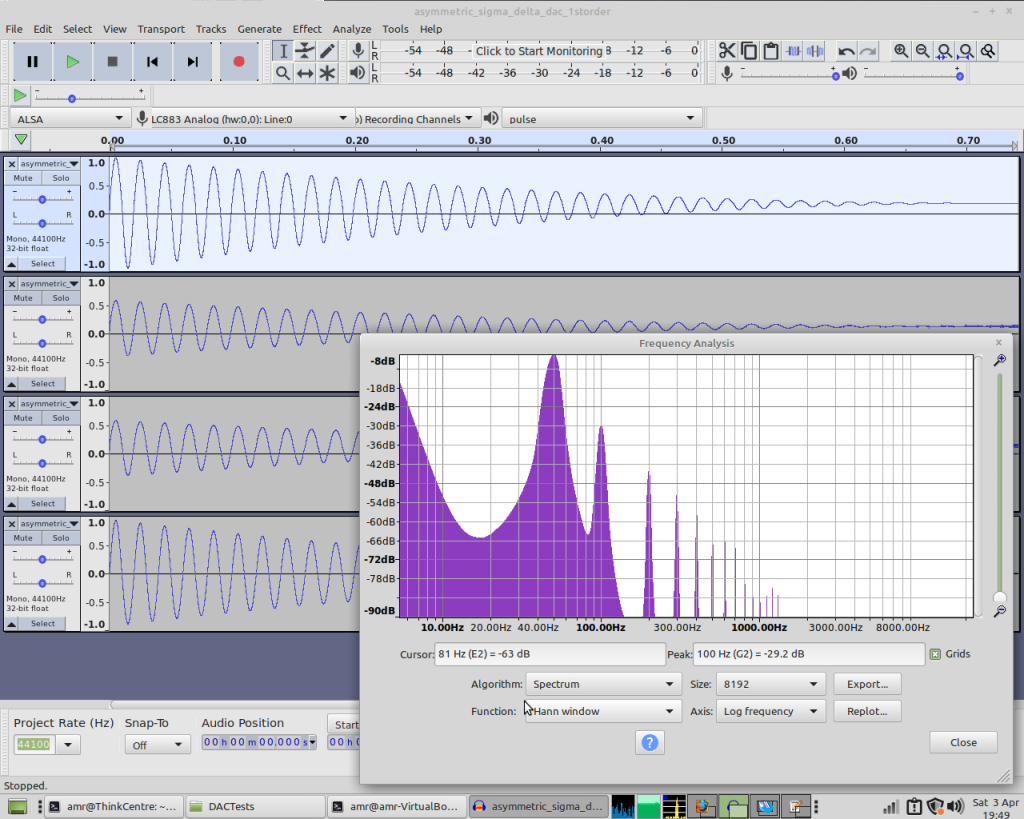
Yeah, that’s not great is it? And the 2nd and 3rd order DACs don’t fare too well either:
And the hybrid DAC?
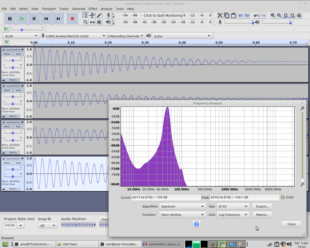
Pretty much unaffected.
So while this isn’t absolute proof, it’s pretty strong evidence that the reason the hybrid DAC performs so much better on real hardware is that the rising and falling edges aren’t symmetrical. Unless it’s saturated, the PWM cycle contains exactly one rising and one falling edge per cycle, whereas in the 1st-order DAC the number of rising and falling edges in a given time period varies in direct proportion to the input value. That’s why the noise takes the form of extra harmonics. With the 2nd- and 3rd- order DACs the number of edges varies pseudo-randomly within a given time-period, hence we see more broad-spectrum noise.
So this experiment has been an interesting exercise in simulation, but also served as a lesson that I shouldn’t rely too much on it!
The testbenches, Makefile and DACs used for this series can be found at https://github.com/robinsonb5/DACTests
Hi again! Happy Easter!
I’m always impressed, how deep you dive in, into the subjects !!!
And I learned a lot today !
THANKS!
Thanks, glad you found it interesting – I do my best to go into enough depth to be interesting (and to adequately cover the subtleties of whichever problem I was trying to solve) while keeping the text reasonably accessible, and without assuming too much prior knowledge – it’s not always an easy balance to strike!
Happy Easter to you too!
I’m not an expert on DACs, but there’s one rule for sigma-delta DAC, that you must not change the sample while a full “run” is not finished, that means 16 cycles in these examples. So I think you should try with 16 ticks here:
https://github.com/robinsonb5/DACTests/blob/main/asymmetric.cpp#L65
Ahh, sorry, I misread the code, tb->d is changed outside the loop.
No worries, thanks for the input anyway – it’s always good to know people are actually reading this stuff and I’m not just talking to myself!
I’m not entirely clear what a “run” would mean in this context, though, and where the 16-cycles comes from? There’s clearly plenty more to learn!
I just re-searched for the source where I read about this:
https://www.xilinx.com/support/documentation/application_notes/xapp154.pdf
(Sampling rate)
But forgot the details, and it’s acceptable to break this rule.
I guess it’s more important for the input to be stable for a sigma delta ADC. Thanks for the app note link – I just noticed they recommend a resistor of at least 2.5K for the RC filter – and that’s with a drive strength of 24mA, we can only do 8mA, and the resistor in the first stage of MiST’s filter is 560 Ohm, I believe. That could well be a big part of the problem – too much load for the outputs to swing quickly and cleanly.
That 3rd order DAC was supplied to me by the MCC216 author for use on the Atari800 core, since I ported it to their board. I’m not sure if he wrote it himself.
One thing I found is that when running two DACs for stereo they interfere with each other. When I used a different clock frequency for each this became much better!
I bought _the_ sigma delta book to try to understand them better. Unfortunately despite working with a bunch of mathematicians and having the internet to research I can’t find out how to interpret their diagrams!
https://www.amazon.fr/Understanding-Delta-Sigma-Converters-Shanthi-Pavan-ebook/dp/B01MT1I21F
Anyway it taught me enough to write my own 2nd order sigma delta for pokeymax. Interesting that the different edges are in fact important, I remember reading that note on opencores. I’ll have to give that technique a try.
The idle tone whisting on 1st order dacs are rather annoying, if the output is not kept at GND when silent. e.g. if using signed audio.
Thanks for the info – I did wonder if that DAC was Frenchshark’s – he once posted what I think was the same one at minimig.net – but with that forum now defunct I couldn’t check.
The cross-channel interference sounds very odd – would be interesting to see whether running the two channels on opposite edges of the same clock is sufficient to reduce it?
I’m glad I’m not the only one who finds those diagrams utterly impenetrable – and it doesn’t help that most of the ones online seem to be concerned with ADC configurations rather than DACs.
I never actually tried the OpenCores one, because that solution reduces the signal amplitude yet further (the audio’s not clean enough on some of my target boards to tolerate that!) – one of the advantages of the hybrid method is that you only need minimal attenuation. (I should also mention that the effect I’ve documented here gets worse as the frequency increases, so it shows up less at low-MHz speeds.)
For what it’s worth, here’s what I came up with for Paula without using multipliers (since PDM + PWM is essentially a multiplier anyway) and is likely much closer to the real hardware.
https://paste.ofcode.org/GF5w4TT88UVEmkBtrLjeSq
That’s really elegant – I like it. Are there any issues with idle tones? (I think there’ll be an audible tone of around 14KHz if a channel is “parked” on a 1 value instead of a zero value? Any audible interactions between higher-frequency idle tones and the PWM?)
Hello there, I haven’t read this blog for a while.
I am really pleased to see those very nice posts on delta-sigma audio DACs.
And yes, the 3rd order DAC verilog code was written by me.
IIRC, it is used in the C64 core and the Amiga core on the MCC216.
The DAC is based on a research paper : http://www.ece.mcgill.ca/~hamoui/FILES/PUBLICATIONS/01257193.pdf
If you like new DAC techniques, I recommend reading this presentation from Bob Adams : https://cscamm.umd.edu/programs/ocq05/adams/adams_ocq05.pdf
Regards,
Frédéric REQUIN aka frenchshark