Part 6 – a sprite and a simple UART
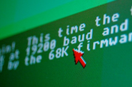
Now that my VGA controller is up and running and I have a hardware text display too, the next step is to think about adding a mouse pointer. There are two ways this is traditionally done – one is to draw the mouse with the CPU, saving and replacing the background image where the pointer obliterates it, and the other is to use a hardware sprite. Since the aim of this project is to learn about FPGAs, going the software route would be a bit of a cop-out! So the last few days of project time have been spent adding a simple hardware sprite, and associated hardware registers for the TG68 to poke.
The requesting and fetching of sprite data is handled by the VGA Cache (which is gradually morphing into a more general DMA cache), allowing the sprite data to be fetched in the “downtime” between scanlines. I’m hoping that as this project progresses I’ll be able to keep all the DMA accesses happening in RAM access slot 1, giving the TG68 free rein of slot 2 (wait states due to bank clashes notwithstanding!)
The sprite is currently 16 pixels square, with four bits per pixel in a “1-bit truecolour” arrangement. Bit 3 indicates opaque/transparent, then bits 2 downto 0 are red, green and blue on/off. I might change this at some point to a proper paletted arrangement, since that would allow 15 colours (plus transparent) rather than just 8.
The other interesting addition this time round is a simplistic UART. There are many UARTs available on OpenCores, some of which are very simple and some of which are very full-featured and complicated. I picked the simplest one I could find, compiled it and saw a Quartus build log full of warnings about latches. I then decided that since this is a learning exercise, I’d write my own simple UART from scratch.
In the process I did learn one very important lesson, which is that it’s not safe to make a state machine switch states based on an asynchronous signal, such as the rxd line from an RS232 serial port.
The problem is that, while a construct such as
if rxd='0' then
  rxstate<=start;
end if
looks to a programmer’s eye as though it should trigger an atomic operation in response to a low level on rxd, that’s not how it works in practice. Instead, in an FPGA, leaving one state and entering another can be quite distinct operations, and if they’re triggered by an asynchronous signal that happens to change too close to a clock edge, it’s possible for one to happen without the other! This leaves the state machine in an illegal state, and usually stalls it.
The solution is very simple – simply delay the rxd signal by one clock, through a register:
if rising_edge(clk)
  rxd_sync <= rxd;
end if;
As simple as that. rxd_sync is guaranteed to show the same state at a rising clock edge even if sampled through different paths, so using that instead of the raw rxd signal results in working state machines.
[Edit: It’s not actually as simple as that. When a signal changes too close to a clock edge it can set up an oscillation (metastability) in the target register which can last for an indeterminate amount of time. It’s possible, though rare, for that amount of time to be longer than a single clock cycle, so to minimise the chances of it causing problems we delay the signal through two synchronisation registers, which effectively squares the tiny probability of a metastable signal wedging the state machine. It still doesn’t eliminate the problem entirely, but makes it so vanishingly unlikely that unless we’re building something that controls a car, a life-support machine or a spaceship, we can safely ignore it.]
The UART currently runs at 19,200 baud, 1 start bit, 1 stop bit and no parity. Characters received are echoed to the screen via the character RAM, and also sent back through the UART, so if you use HyperTerminal you’ll see what you’re typing.
The ultimate goal here is to be able to bootstrap the system over the serial port, uploading program code to be executed. This will avoid having to recompile the entire project every time the code changes.
One other minor change this time round: the master clock frequency has been increased from 100Mhz to 112.5 Mhz. In the process I’ve added some timing constraints to the SDRAM interface and made a few other tweaks which were necessary to make it stable at that speed.
Full source and binary for anyone who might be interested, available here.

