
Part 2: Hello World
Since my last post I’ve received yet another board from Emanuel – another prototype FPGA board with Spartan 6, SDRAM and SSRAM. This one’s a little simpler than the previous board, with no ports other than USB on the board itself, and a daughter card with a VGA connector on it. Unlike the previous board, which had a 2-bits-per-gun resistor ladder DAC, this one has an ADV7123 video DAC chip – the same one used on the DE2 board – which has an impressive 10 bits per gun. That’s good enough to do 24-bit true colour with headroom for calibration tables!

So, let’s get “Hello World” running on this board.
I’m going to use the ZPUDemos repository, which I’ve tagged at the appropriate point, so we can check it out like so:
git clone https://github.com/robinsonb5/ZPUDemos
cd ZPUDemos
git checkout 20131228_1
git submodule init
git submodule update
You should now have a clean copy of the repo.
We need to add the following files
In HelloWorld/fpga/ we need to add a directory for the new board – so:
mkdir HelloWorld/fpga/ems11-bb21
Now it’s time to fire up ISE and create a new project.
Specify /path/to/ZPUDemos/HelloWorld/fpga/ems11-bb21/ as the path to the new project, and call it “HelloWorld”. ISE will want to create a HelloWorld subdirectory, but that’s unnecessary here.
Now we need to specify the device, which in this case is family: “Spartan 6”, Device: “XC6SLX45”, Package: “FGG676”. Also set the preferred language to VHDL, then click through to the end of the New Project wizard.
We need to create a toplevel file for the new board, which will be filed in the “ZPUDemos/RTL” directory. We also need a .ucf file to specify pin mappings. I have a .ucf file for the board, which has been automatically generated from the schematics – but the signals are all commented out by default, and some signal names need changing since they’re not valid in VHDL. So we’ll take a gradual approach, and enable them bit by bit. The .ucf file will go in ZPUDemos/Board/
For “Hello World” we only actually need two pins defined. We need a clock input, and we need an RS232 serial output. These we can find on pin D14 for a 50MHz clock input, and L18 for the signal called “RXD1(FROM_FPGA)”. We can’t use brackets for VHDL signal names, so we’ll rename that to RXD1_FROM_FPGA. (That’s rxd from the perspective of the attached computer, not the FPGA. That’s why I like the SPI nomenclature – Master In, Slave Out is completely unambiguous regarding direction!)
So the 50MHz input clock is specified in the .ucf file like so:
NET "CLK50" LOC = "D14";
NET "CLK50" IOSTANDARD = LVTTL;
NET "CLK50" TNM_NET = "CLK50" | CLOCK_DEDICATED_ROUTE = FALSE;
TIMESPEC "TS_CLK50" = PERIOD "CLK50" 20 ns HIGH 50 %;
The board has two RS232 interfaces available to the FPGA – both of which are carried over a single USB cable – for now we’ll only define one of them, but we will define all four signals, not just the one required for Hello World:
NET "RXD1_FROM_FPGA" LOC = "L18";
NET "N_CTS1_FROM_FPGA" LOC = "K19";
NET "N_RTS1_TO_FPGA" LOC = "H24";
NET "TXD1_TO_FPGA" LOC = "F24";

NET "RXD1_FROM_FPGA" IOSTANDARD = LVTTL;
NET "N_CTS1_FROM_FPGA" IOSTANDARD = LVTTL;
NET "N_RTS1_TO_FPGA" IOSTANDARD = LVTTL;
NET "TXD1_TO_FPGA" IOSTANDARD = LVTTL;
The simplified first-approximation toplevel file looks like this:
-- Toplevel file for EMS11-BB21 board

library ieee;
use IEEE.STD_LOGIC_1164.ALL;
use IEEE.numeric_std.ALL;

entity EMS11_BB21Toplevel is
port
(
    CLK50 : in std_logic;
    TXD1_TO_FPGA : in std_logic;
    RXD1_FROM_FPGA : out std_logic;
    N_RTS1_TO_FPGA : in std_logic;
    N_CTS1_FROM_FPGA : out std_logic
);
end entity;

architecture rtl of EMS11_BB21Toplevel is

begin
N_CTS1_FROM_FPGA<='1';  -- safe default since we're not using handshaking.

project: entity work.VirtualToplevel
    generic map (
        sysclk_frequency => 500 -- Sysclk frequency * 10
    )
    port map (
        clk => CLK50,
        reset_in => '1',

        -- UART
        rxd => TXD1_TO_FPGA,
        txd => RXD1_FROM_FPGA
);

end architecture;
So having added the toplevel and the .ucf file to the project, we also need to add the following files:
- HelloWorld/Firmware/HelloWorld_ROM.vhd
- HelloWorld/RTL/HelloWorld_VirtualToplevel.vhd
- HelloWorld/RTL/Toplevel_config.vhd
- RTL/simple_uart.vhd
- ZPUFlex/RTL/zpu_core_flex.vhd
- ZPUFlex/RTL/zpupkg.vhd
- ZPUFlex/RTL/zpu_config.vhd
The project should now compile, and when uploaded via JTAG, should send “Hello World” to one of the RS232-over-USB ports. 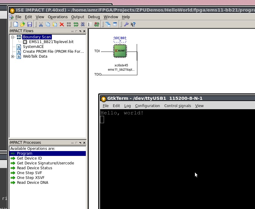
how can I lay my hand on one of these boards