
Achieving 24-bit colour on a 15-bit device – 2021-12-31
[I found this unfinished post in a dusty corner of my drafts folder, and decided that tonight was the night to finish it!]
While I’m sitting through the all-too-familiar wait while Quartus builds a core, I wanted to write a few words about dithering and how I approached the problem of doing 24-bit colour video output on a platform which has only 15 bits of colour resolution on its VGA port.
The video DAC on the Turbo Chameleon 64 has just 5 bits per colour gun which means we can output 32 different levels each of red, green and blue for a total range of 32,768 colours. This is fine for the ECS Minimig core, since the original Amiga has only 4 bits per gun, for a total of 4,096 colours – but the AGA chipset doubles this colour depth to 8 bits per gun, full 24-bit output – so some compromises will be needed.
If we don’t do any dithering, and simply take each eight-bit value [a b c d e f g h] and truncate it to five bits, then we’re effectively rounding the value down to [a b c d e 0 0 0]. The idea of dithering is to selectively add a dither value to the lower bits [f g h] before the truncation. If the result of this addition spills into the upper five bits, then we’ve rounded the value up instead of down. By rounding some pixels up and some pixels down we can create the illusion of extra levels of precision in the output.
[It’s no accident that there are strong parallels between this and the audio noise-shaping I’ve been exploring in earlier posts. Once again, we’re seeking to modulate a signal before applying a threshold function, in order to make the noise less objectionable. In this case we’re adding a predetermined high-frequency signal to lift the quantization noise beyond the frequency band occupied by the interesting parts of the signal, and relying on the eye – and it’s inability to see individual pixels – as a low-pass filter.]
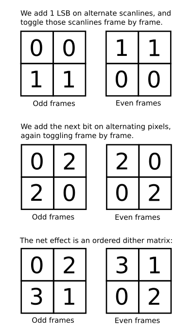
In the past I’ve used two methods together to add two extra bits of colour precision – namely, rounding up alternate pixels by adding a ‘1’ to dither bit [f], and rounding up alternate complete scanlines by adding to dither bit [g]. In both cases I would switch which pixel or scanline was dithered on a frame-by-frame basis, to hide the dithering in a faint shimmer.
I realise now that my approach is basically just using a 2×2 ordered dithering matrix, but inverting it on a frame-by-frame basis.
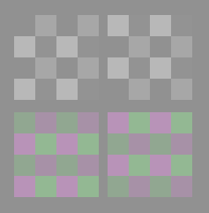
Having gained that insight, it occurred to me that I could hide some of the intensity change and shimmer from dithering by using different matrices for the red, green and blue channels. I found that the best results came from dithering red and blue using one matrix, and using its inverse for green – then inverting the whole matrix every frame.
The following illustration shows an exaggerated impression of how the dithering looks on even and odd frames when it’s applied to all three channels together, and how it looks when it’s split between green and red/blue. The latter arrangement significantly reduces the change in contrast from frame to frame, and thus the amount of perceived flicker.
Since the 2×2 matrix gives me two bits of dither, but we actually need three bits for the Turbo Chameleon 64, I applied a simple Linear Feedback Shift Register to the lowest bit, to provide some random dithering as well. On the MiST board this isn’t necessary since we have a six-bit DAC available for each channel. On the de10-lite, which I use for development, I only have four bits per gun, so I add two extra bits of dither with the LFSR. This does produce visible noise in areas of solid colour, but it’s actually not that objectionable – almost calling back to the little bit of noise you’d see when using a TV with an RF modulator!
Very interesting. I especially like the temporal dithering to reduce the noticeable dithering which is especially obvious at 4-bits. Alternating the RB and G might cause some perceptual saturation loss, but that’s probably fine.
Have you thought about about applying that dither beyond the resolution of one pixel? The 64’s pixel clock is like only ~7.8MHz so I’m sure an 8x or even 16x oversample would be possible.
Oversampling’s an interesting idea – I think it would look great on a CRT, but I don’t think it would work so well on LCDs because they sample-and-hold on their own pixel clock, so will see the pixel level at an “instant”, rather than averaged over the duration of a pixel.
Having said that, the TC64’s output is quite soft, so it might work better on that device than it would on one with sharp video output!
(Interesting point about potentially losing saturation – my gut says it shouldn’t be an issue, simply because full-scale values are clamped, so fully saturated colours shouldn’t see any dithering at all – but I’d have to run some tests to be certain.)