2022-05-14
Continuing my experiments with the IceSugar-Pro board, building cores using Yosys and friends, I now have EightThirtyTwoDemos running, using PMODs to provide VGA out, I2S audio out, PS/2 keyboard and mouse, and SD card. (The latter isn’t strictly necessary since the FPGA board already has an SD card slot – but it’s on the underside of the board and impossible to access while the IceSugar-Pro is inserted into the carrier board.)
So how did I go about wiring up the PMODs?
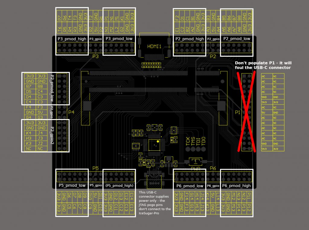
There’s comprehensive pin documentation for the connectors on the carrier board at https://github.com/wuxx/icesugar-pro/tree/master/schematic – but I was very keen not to have to refer to that, and go through a tedious, error-prone pin mapping process every time I changed my mind about which connector should carry a particular peripheral. At first glance we appear to have six identical connectors, labelled P1 through P6, so I wanted to be able to allocate peripherals by connector name, and not have to worry about the individual pins.
There are a few complications with that plan:
- P1 doesn’t carry any useful signals, and if populated, prevents the USB-C cable from being connected!
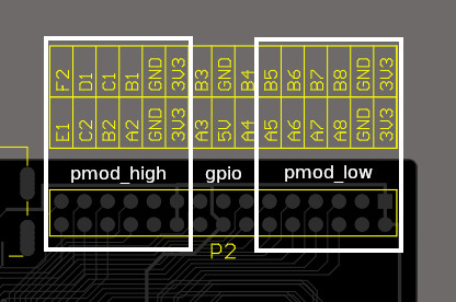
- P2, P3 and P6 each carry two sets of two-row PMOD-compatible pins, as well as four extra GPIOs and +5v supply in between.
- P4 has two pins unconnected, but otherwise matches P2, P3 and P6.
- P5 is fully connected, but the DAPLink on the carrier board interferes with four pins. P4 and P5, therefore, each provide only one usable set of PMOD pins.
So we have eight usable two-row PMODs and some random extra GPIOs.
Since we want to be able to reference the eight PMODs individually, what I’ve done is split each of the connectors into a “high” part, a “low” part and a “gpio” part for the extra signals in the middle, like so:
The (VHDL) toplevel for the board, declares the ports thusly:
P2_pmod_high : inout std_logic_vector(7 downto 0);P2_gpio : inout std_logic_vector(3 downto 0);P2_pmod_low : inout std_logic_vector(7 downto 0);P3_pmod_high : inout std_logic_vector(7 downto 0);
...
I then assign a peripheral to the appropriate ports like so:
alias i2s_pmod is P2_pmod_high;It’s hard to imagine any way that could be easier!
I created a package to define the PMOD pin numberings, like so:
-- Pin numberings for PS/2 PMODconstant PMOD_PS2_KDAT : integer := 0;constant PMOD_PS2_MDAT : integer := 1;constant PMOD_PS2_KCLK : integer := 2;constant PMOD_PS2_MCLK : integer := 3;
The PS/2 PMOD is a special case, because it only has one row of pins, so only needs to use half the allocated PMOD. Which half?
-- PS/2 keyboard and mouseconstant ps2_pmod_offset : integer := 4;alias ps2_pmod is P6_pmod_high;
By defining an offset, I can select between the top or bottom row of pins – an offset which is taken into account when instantiating the drivers.
That leads me to the other complication with this scheme. For maximum flexibility I wanted to declare all the PMOD IOs as “inout”, and let their subsequent usage determine the effective data direction. This is where Yosys throws a bit of a spanner into the works, because it has only the most rudimentary support for tristate signals, and I’m told it’s best to instantiate pin drivers manually. For ECP5 devices, the component we need for this is TRELLIS_IO. I declare the component, complete with generic { DIR : string := “BIDIR” }. The actual wiring to the nominated connector, bringing together the multiple threads of tri-state IO, the aliased connector name and the pin offset, looks like this:
ps2kd : component TRELLIS_IO port map ( B => ps2_pmod(PMOD_PS2_KDAT+ps2_pmod_offset), I => '0', T => ps2k_dat_out, O => ps2k_dat_in );
ps2kc : component TRELLIS_IO port map ( B => ps2_pmod(PMOD_PS2_KCLK+ps2_pmod_offset), I => '0', T => ps2k_clk_out, O => ps2k_clk_in );
ps2md : component TRELLIS_IO port map ( B => ps2_pmod(PMOD_PS2_MDAT+ps2_pmod_offset), I => '0', T => ps2m_dat_out, O => ps2m_dat_in );
ps2mc : component TRELLIS_IO port map ( B => ps2_pmod(PMOD_PS2_MCLK+ps2_pmod_offset), I => '0', T => ps2m_clk_out, O => ps2m_clk_in );
Notice that the PS/2 out signals are connected to ‘T’, the tristate signal – and not to ‘I’, which is tied to ‘0’. This gives us open-collector semantics, where the port is either high-Z or driven low.
The complete port mapping for the carrier board looks like this: