Part 2: A VGA controller
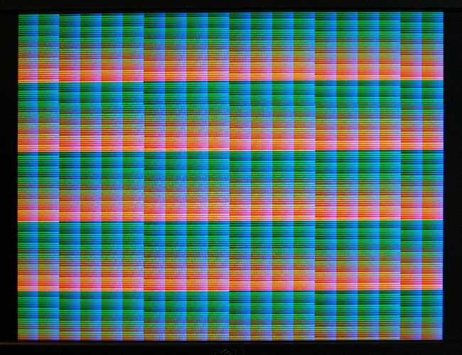
My first experiments with the TG68 processor didn’t involve RAM at all – it simply ran from a tiny hard-coded ROM and poked an incrementing counter into a hardware register. In preparation for getting the processor working from RAM I’ve been experimenting with the SDRAM controller from the Minimig Project, and having combined it with the simple VGA timings generator used in the Chameleon Pong core, I now have a working VGA framebuffer
The DE1 Minimig’s SDRAM controller runs on a fixed 16-state cycle, using 4-word bursts, so it can move a maximum of 64 bits per round-trip. I use the same clock for SDRAM and VGA master clock, and at 640×480 pixels, I need one pixel every 4 clocks. I’m using 16-bits per pixel (5-6-5 hi-colour), so the display needs 4 words or 64 bits every 16 clocks, which means while data’s being displayed it’s saturating the SDRAM controller.
Luckily there are various tricks we can employ to provide extra bandwidth. The most obvious one, using a smarter, more dynamic SDRAM controller isn’t actually ideal, because generally speaking the smarter a controller is the less predictable its response time will be. The other reason I didn’t want to toss out the controller completely and start again is that I wanted to be able to bring any improvement I made to the controller back into the Minimig project. (The third reason, of course, is that writing a good SDRAM controller is *hard*!)
SDRAM is organised into banks, and the chip used in the DE1 board uses four of them. These are more-or-less independent, so it’s possible to start a read on one bank while a read to another is still taking place. This means that it’s possible to add a second time-slot to the SDRAM controller, 180 degrees out of phase with the first. All I have to do is ensure that I don’t allow the same bank to be accessed from both slots.
I split the RAM up such that adjacent 4-word bursts would come from different banks, like so:
|----------- bank 0 ---------|--------- bank 1 ----------|--------- bank 2 ----------
  word0  word1  word2  word3  word0  word1  word2  word3  word0  word1  word2  word3
 | 0  1 | 2  3 | 4  5 | 6  7 | 8  9 | A  B | C  D | E  F | ...
Because both the reading and writing processes in my design would be accessing memory sequentially, arranging the banks this way should prevent either process being held off for more than one slot.
The other thing I needed to take care of was refresh cycles. Since both slots need to be held off while a refresh happens, I needed to prevent them happening while data was being displayed, so simply arranged for them to happen at the end of each scanline.
For anyone that’s interested, the demo project can be downloaded here.
There are still a couple of timing glitches, but if you see them, pressing the reset button (key0) a few times should clear it. The fill rate isn’t great, but that’s because writes are currently not happening in burst mode, so only one word at a time is written. This means it takes at least four full frames to write to the entire screen.
The TG68 processor isn’t actually involved in this part of the project – instead there’s a simple hardware process filling the frame. The next stage will be making the TG68 draw something.

