
Part 5 – Adding a Menu
Having talked in depth about the hardware in previous parts, in this part I’m going to talk about the software side of things.
I mentioned before that the character ROM contains 128 characters which, from characters 32 upwards, are standard 7-bit ASCII. I’ve added some special characters in the lower 32 character slots, however, which have uses in drawing the OSD. The extra characters are as follows:
- 0 – 7: solid blocks 7 pixels high, 1 to 8 pixels wide, left aligned in the character cells. Useful for drawing progress bars.
- 8 – 15: As above but right-aligned within the character cell. May be useful in progress bar applications but I haven’t actually used these yet, so might eventually reassign them.
- 16 – 19: Arrow heads, pointing right, left, up and down, respectively. (The right arrow is used as a cursor in the menu.)
- 20: Checkmark
- 21: Cross
- 22: Cycle
- 23: ellipsis
- 24 – 31: Currently unused
For the OneChipMSX and FPGA PC Engine cores I put together a simple, lightweight data-driven menu system, which can be found in CtrlModule/Firmware/menu.[c|h]
The menu is defined as an array of menu_entry structures, which look like this:
struct menu_entry
{
	enum menu_entry_type type;
	char *label;
	menu_action action;
};
where menu_action is a 32-bit integer whose meaning varies according to the type, and menu_entry_type can be one of the following:
- MENU_ENTRY_NULL – a NULL entry to terminate the current menu.
- MENU_ENTRY_TOGGLE – An on/off switch. Menu action is set to a bit number, and the specified bit is toggled within a MENU_TOGGLE_VALUES variable which can be access from the main program.
- MENU_ENTRY_CALLBACK – A function, a pointer to which should be in Menu action, will be called when this menu item is selected.
- MENU_ENTRY_CYCLE – Instead of a single string, label should point to an array of strings, and action should be set to the number of options to be cycled through. The macro MENU_CYCLE_VALUE() can be used to retrieve (or set) the index of the currently selected entry.
- MENU_ENTRY_SUBMENU – Menu action should point to another array of menu_entry structures defining a submenu.
- MENU_ENTRY_SLIDER – Menu action should be set to the maximum slider value. This will also set the width of the slider in characters, so make sure the width of the slider plus its label will fit on screen! The current value can be retrieved (or set) using the MENU_SLIDER_VALUE() macro.
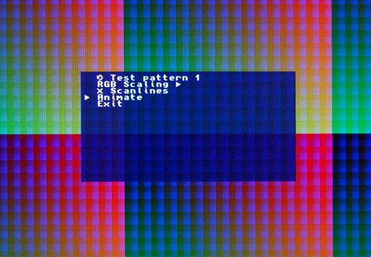
The menu pictured above can be defined as follows:
// Test pattern names
static char *testpattern_labels[]=
{
	"Test pattern 1",
	"Test pattern 2",
	"Test pattern 3",
	"Test pattern 4"
};

// Our toplevel menu
static struct menu_entry topmenu[]=
{
	{MENU_ENTRY_CYCLE,(char *)testpattern_labels,MENU_ACTION(4)},
	{MENU_ENTRY_SUBMENU,"RGB Scaling \x10",MENU_ACTION(rgbmenu)},
	{MENU_ENTRY_TOGGLE,"Scanlines",MENU_ACTION(0)},
	{MENU_ENTRY_CALLBACK,"Animate",MENU_ACTION(&TriggerEffect)},
	{MENU_ENTRY_CALLBACK,"Exit",MENU_ACTION(&Menu_Hide)},
	{MENU_ENTRY_NULL,0,0}
};
The array of labels is used by the Cycle entry that’s first in the list. The fourth menu entry references TriggerEffect, which is a callback function that will be called when the “Animate” menu entry is selected. (Notice the “\x10” in the RGB Scaling label, which renders a right-arrowhead as part of the label, indicating the presence of a submenu to the user.) The RGB Scaling entry references a submenu, rgbmenu, which is defined like so:
// RGB scaling submenu
static struct menu_entry rgbmenu[]=
{
	{MENU_ENTRY_SLIDER,"Red",MENU_ACTION(16)},
	{MENU_ENTRY_SLIDER,"Green",MENU_ACTION(16)},
	{MENU_ENTRY_SLIDER,"Blue",MENU_ACTION(16)},
	{MENU_ENTRY_SUBMENU,"Exit",MENU_ACTION(topmenu)},
	{MENU_ENTRY_NULL,0,0}
};
Now to run the menu, we simply call Menu_Set(topmenu); followed by Menu_Show();, then call Menu_Run(); within the inner loop. I’ve added some extra hardware registers to give this demo more to do, but there’s nothing remarkable about them, so I won’t describe them in detail.
Our main() now looks like this:
int main(int argc,char **argv)
{
	int i;
	int dipsw=0;
	PS2Init();
	EnableInterrupts();
	OSD_Clear();
	Menu_Set(topmenu);
	for(i=0;i<4;++i)
	{
		PS2Wait();	// Wait for an interrupt - most likely VBlank, but could be PS/2 keyboard
		OSD_Show(1);	// Call this over a few frames to let the OSD figure out where to place the window.
	}
	MENU_SLIDER_VALUE(&rgbmenu[0])=8; // Set default values for the sliders
	MENU_SLIDER_VALUE(&rgbmenu[1])=8;
	MENU_SLIDER_VALUE(&rgbmenu[2])=8;
	Menu_Show();
	while(1)
	{
		struct menu_entry *m;
		HandlePS2RawCodes();
		Menu_Run();

		dipsw=MENU_CYCLE_VALUE(&topmenu[0]);	// Take the value of the TestPattern cycle menu entry.
		if(MENU_TOGGLE_VALUES&1)
			dipsw|=4;	// Add in the scanlines bit.
		HW_HOST(REG_HOST_SW)=dipsw;	// Send the new values to the hardware.
		HW_HOST(REG_HOST_SCALERED)=MENU_SLIDER_VALUE(&rgbmenu[0]);
		HW_HOST(REG_HOST_SCALEGREEN)=MENU_SLIDER_VALUE(&rgbmenu[1]);
		HW_HOST(REG_HOST_SCALEBLUE)=MENU_SLIDER_VALUE(&rgbmenu[2]);
	}
}
Full source for the project is on GitHub, tagged as Step4
it is tagged as Step4, not Part4 😉
Otherwise EXCELLENT JOB!
Well spotted – I’ll correct that now – thanks 🙂