
[This is a post I made to AmiBay back in 2011. The domain on which I hosted the images and audio snippets is about to expire, so I’ve rescued the files and moved them here – so I may as well archive the post itself too, while I’m at it!]
Anyone remember CU Amiga Magazine’s ProjectXG feature many years ago? They published a parts list and instructions in the magazine for interfacing a Yamaha DB50XG WaveBlaster MIDI daughterboard, intended for use with a PC soundcard, to an Amiga.
There were some major flaws in the project, not least that the project box in the parts list had screw pillars in the corners so the board didn’t quite fit! (On the mailing list people were advocating getting around this by snapping the corners off the board!)
The article also advocated wiring it up as a “rats nest”, rather than using any kind of circuit board.
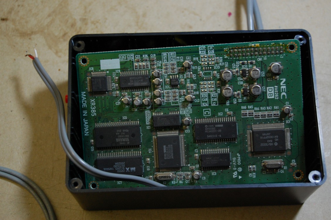
Having dug out my Amiga gear recently, and having seen an EBay seller selling similar cards (NEC XR385, rebadged DB60XG) really cheap, I couldn’t resist revisiting the old project and making another ProjectXG!
(I sold my original box on AmiBay, and the buyer suggested / requested the useful addition of a MIDI pass-thru. I’d already added a MIDI-In socket, but the buyer wanted a MIDI-Out socket so events from OctaMED could be sent to a drum machine as well as the XG card. I’ve included both MIDI ports in the new box.)
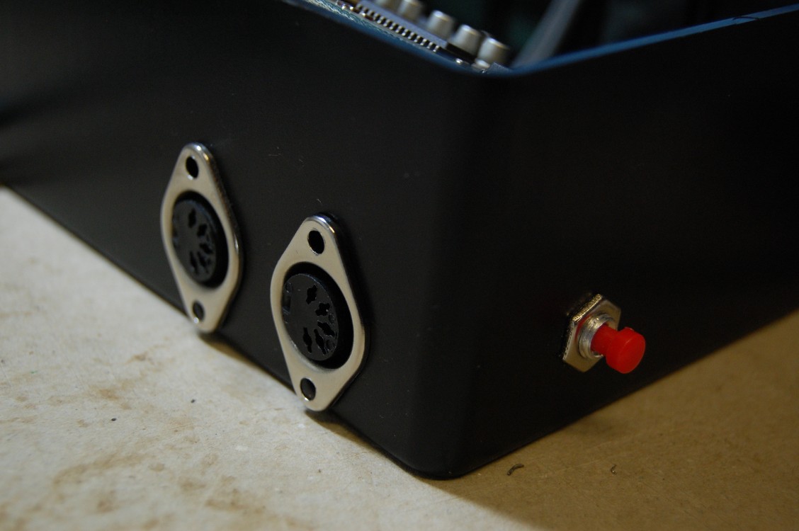
Firstly, here’s the MIDI sockets and reset button:
Then the circuit board itself. (Yes, I fed the wrong wire through the wrong hole – but it was all soldered up by the time I realised!)
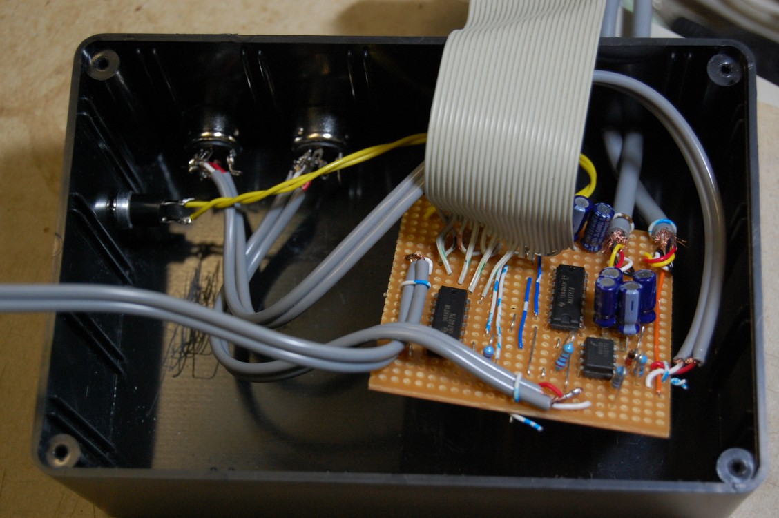
The cable is an old 40-conductor IDE cable, cut down and the wires I don’t need removed. I know from the first time round that soldering directly to a freestanding header is a *nightmare* job – the plastic melts *so* easily, allowing the pins to fall off. So instead I used the original socket from the IDE cable, and plugged a 26-pin length of right-angle header into that, giving me a 26-way header wired and ready to plug into the XG board. (The IDE plug needs to be one that *doesn’t* have a key pin blocked.) One nice thing about this is that the odd numbered pins on the Waveblaster header are (nearly) all grounds, so all the signal wires in the ribbon cables are separated by at least one ground wire.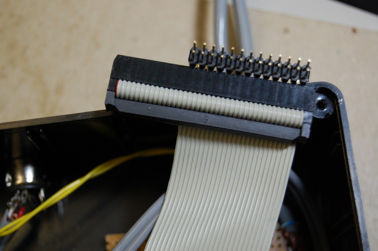
The card plugged onto the header and sitting diagonally in the box. It actually fits very nicely diagonally, and the cable has enough spring in it to hold the card nice and tight against the lid when it’s closed. Even with no anchoring, nothing rattles around in the box once it’s closed.
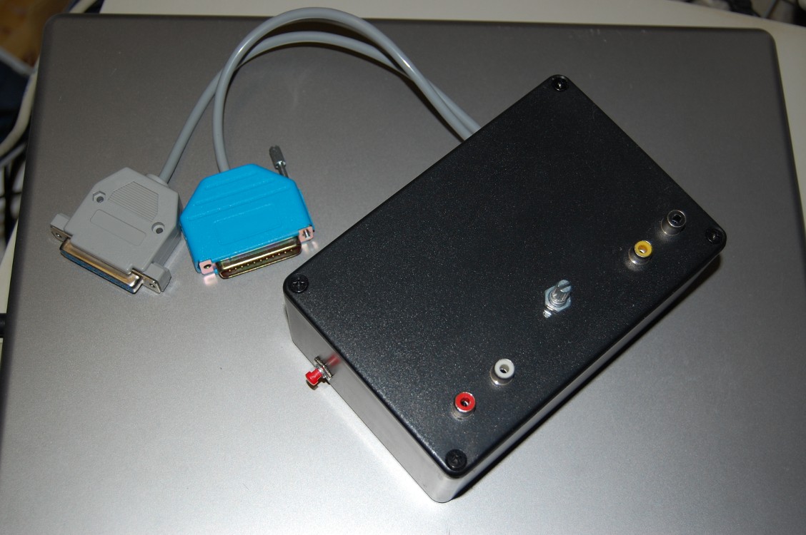
The finished box with audio in and out, and a 10K linear mixer pot attached to the lid. The two cables go to the serial port (for +/-12v and serial in/out) and the disk drive port (for +5v power) (The blue hood has only one support pillar because it’s a DB25 hood on a DB23 connector!)
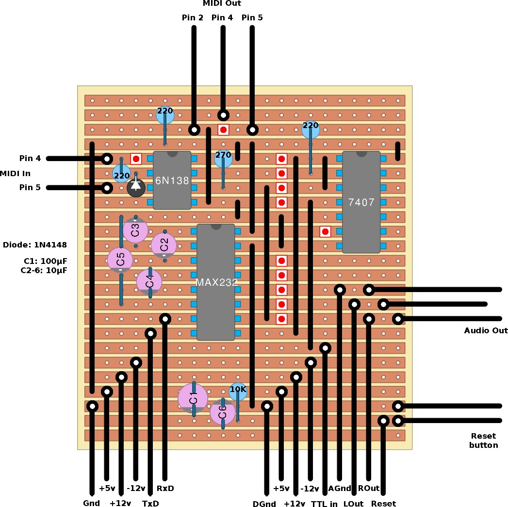
Stripboard layout, in case anyone else wants to have a go at this: The red blobs indicate a strip cut. Not shown are more cuts between opposite pins of each chip, which are obviously also required!
A few recordings, made using the first box I made, and my Amiga 4000. (One track played using OctaMED SoundStudio, the others with my B5MIDI DeliPlayer which can be found on Aminet.)
And a couple more recorded using the XR385…
Hi, in the pictures you’re showing the audio in phono and the volume potentiometer on the lid.
I was wondering how you had these wired up?
I totally appreciate this feature is over 10 years old now, but I’m in the middle of building the interface (almost completed), and realised I only have audio out, no passthrough.
Apologies for not spotting your comment sooner.
All I did with the volume pot was to wire the Amiga and DB50XG audio signals to opposite ends of the pot, and wire the output to the tap/wiper. This is absolutely not the correct way to mix audio, but at the time I didn’t know that! 😉
Hope the interface works well for you, and you have fun with it.