The Cyclone III board I’m using has a nice roomy EP3C25 FPGA with about 25,000 logic elements and 32 meg of SDRAM, but is rather lacking in ports for talking to the outside world. I plan to add an RS232 serial port to the power board which featured in my last post, just as soon as I receive the requisite components.
The power board connects to the two least useful of the board’s GPIO headers; most of the IOs on these headers are used up by the SDRAM, but the other two GPIOs are almost fully functional. (On the EP3C16 version of the board, all 36 IOs on these headers are available – but the EP3C25 needs more power pins, so a few of the IOs are unavailable to me.)
In approximate order of importance, the ports I want to add to this project are:
- VGA
- PS/2 keyboard and mouse
- Audio
- SD card
- Joystick (9-pin DSub, Atari/Amiga style)
- Ethernet – if at all possible.
The VGA port requires three individual resistor ladder DACs, which means a fairly high component count, so I wasn’t keen to try building this particular interface on stripboard. Therefore I decided to try having a custom PCB made.
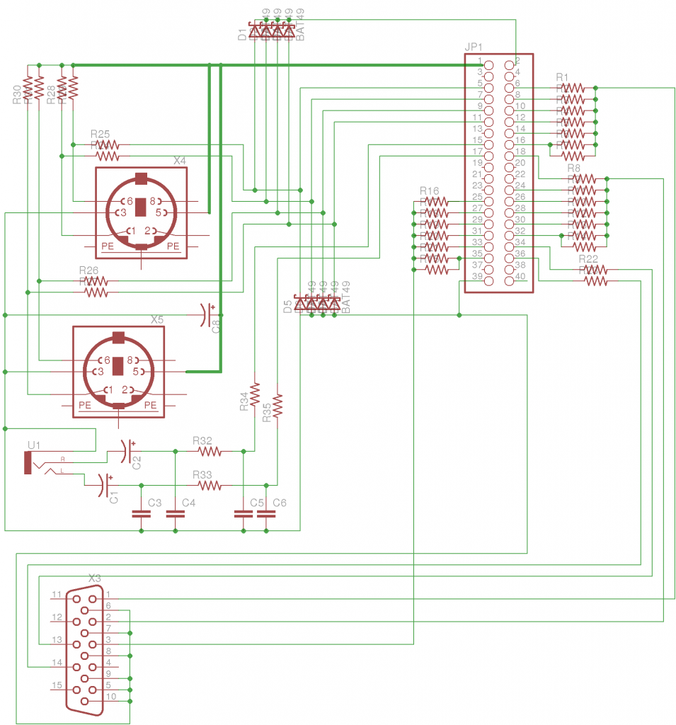
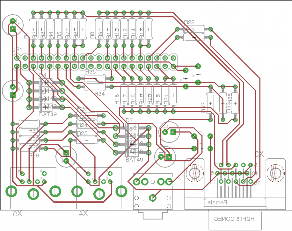
I used the freeware edition of Eagle to produce the schematic of my board and lay it down, and learned a great deal in the process. Since including just the VGA port would have been a waste of the remaining pins on the header, I also included the PS/2 ports and audio port on this board (using the DE1 and Minimig schematics as reference).
I made a few mistakes in the process, which I shall avoid next time! Most importantly, I wasn’t entirely clear about which side of the board was which. I now know that by default components placed in Eagle are assumed to be on the top layer of the board, with through-hole components being soldered at the back – but I routed the traces on the top layer, intending to treat that as the solder-side and place the components on the other side. I’d correctly flipped the components to deal with this, but it confused the PCB fab house and delayed things a little. What I should have done was place everything the right way round, then route the traces onto layer 16 (the back of the board) instead of layer 1.
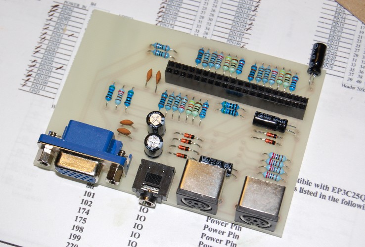
I used Futurlec to make the PCBs; they seem to be the most affordable option for a hobbyist who only wants a couple of boards. Because I’d opted for the cheapest shipping method, the boards took a couple of weeks to arrive, but I received them on Friday, and have almost finished populating the first one!
This board attaches to J1 on the FPGA board, and provides a 6-bit resistor ladder for each colour, giving a theoretical 262,144 colours without dithering.
I haven’t yet tested the PS/2 sockets, since I’m waiting for a delivery of the right value of resistor to complete the board – but once it’s verified as working I’ll make the Eagle files available for download.
The 6-bit resistor ladder probably deserves some explanation, since it was an interesting problem to solve. The VGA specification says that the maximum voltage on the R, G and B pins should be 0.7v, and the load on these pins (i.e. the monitor) should have an impedance of 75 ohms. The FPGA either drives each pin to +3.3v or to gnd, so the FPGA, the resistor ladder and the load form a complicated potential divider.
Since it’s non-trivial to calculate the voltage produced for an arbitrary input to the resistor ladder, I created a spreadsheet to do the job, and found a combination of standard value resistors that would give a maximum value very close to 0.7v.
The spreadsheet, in case anyone’s interested, can be found here.
The resistor values I settled on were:
- 525R (formed with a 1K and 1K1 in parallel – which, yes I know, adds a large potential error where you want it least, but also gives you scope to trim that error by swapping resistors in the hope of finding a good match.)
- 1K1
- 2K2
- 4K3
- 9K1
- 18K
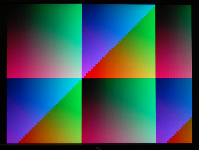
So does it work? As always, a picture speaks a thousand words:


Hi AMR, I’m looking for a VGA board that I can connect to my microcontroller. Can you suggest any? I’ve designed a VGA board but the microcontroller I’m usng is too slow and the highest res I can get out of it is 255x480x256 colours.
I need at leat 1024×768 res. Any ideas? Please let me know. Thanks mate.
Pete
To be honest I don’t have all that much experience with such things – what I document here is my own learning process. If I were to require such a thing myself, however, I would probably buy a small FPGA dev board with SDRAM onboard – maybe something like this: http://www.ebay.co.uk/itm/FPGA-CORE-Board-EP4CE6E22-with-SDRAM-Powerful-Cyclone-IV-/290738985130?pt=LH_DefaultDomain_0&hash=item43b164d8aa
Then put an SDRAM and VGA controller on the FPGA. You’d have to create an interface between the microcontroller and FPGA (make sure the µC outputs at 3.3v since the FPGA’s not 5v tolerant) and the drawing speed would probably be low, because just displaying that resolution will take a lot of RAM bandwidth.
That’s just how I’d approach it, though – and I’d do it that way because that’s what I know. There may well be a better solution.
This is a very mundane question, but where did you get JP1, and what is that connector actually called? I can find them as IDC assemblies for ribbon cables, but not PCB mount…
I got them on EBay – after a bit of experimentation I hit upon the search term “2×20 PCB header”!