Part 1: a counter
The TG68 softcore processor is an MC68000-compatible processor core written by Tobias Gubener, and used in the DE1, DE2 and Turbo Chameleon 64 ports of the Minimig project. The latest version of the core also supports most 68020 instructions,making it a pretty powerful and useful general purpose processor for FPGA applications.
As a learning exercise I wanted to try using the TG68 in a minimal project – a first step towards the “build-my-own-computer” dream I alluded to in an earlier post.
The TG68 consists of two layers – there’s the processor core itself which has a pretty simple interface, then there’s a wrapper which makes it largely signal-compatible with a “real” 68k processor. For this project I’ve used the wrapper – but later projects will show how the processor can be used “bare”.
To test the processor, I’ve created a very simple program, assembled with Easy68k.
ORG    $0000
    dc.l      $0      ; Initial Stack Pointer
    dc.l      $8      ; Initial Program Counter
START:                ; first instruction of program
    addq.w    #1,d0
    move.w    d0,$dff180
    bra.s    START

    END    START        ; last line of source
This program runs in a loop which increases register D0 by 1 each iteration, and writes the new value to location $dff180. (This is the location of the background colour register in the Amiga’s custom chipset – so this program, running on an Amiga, would result in a colourful flickering screen, similar to many decrunchers back in the day.)
The minimal program above assembles to a mere 5 words:
$08: $5240
$0A: $33C0
$0C: $00DF
$0E: $F180
$10: $60F6
(Note that the longword at location 0 is the initial Stack Pointer, and at location 4 is the initial Program Counter, so we start the actual program at location 8.)
In the interests of getting the processor up and running with as little effort at possible, I’ve not attempted to run the program from RAM – instead I decode the appropriate addresses directly in VHDL, like so:
process(clk,cpu_addr)
begin
    if rising_edge(clk) then
        if cpu_as='0' then    -- The CPU has asserted Address Strobe, so decode the address...
            case cpu_addr(23 downto 0) is
                -- We have a simple program encoded into five words here...
                when X"000006" =>
                    cpu_datain <= X"0008"; -- Initial program counter.  Initial stack pointer and high word of PC are zero.
                    cpu_dtack<='0';
                when X"000008" =>
                    cpu_datain <= X"5240";  -- start: addq.w #1,d0
                    cpu_dtack<='0';
                when X"00000A" =>
                    cpu_datain <= X"33c0";  -- move.w d0...
                    cpu_dtack<='0';
                when X"00000C" =>
                    cpu_datain <= X"00DF";  -- ...
                    cpu_dtack<='0';
                when X"00000E" =>
                    cpu_datain <= X"F180";  -- ...,$dff180
                    cpu_dtack<='0';
                when X"000010" =>
                    cpu_datain <= X"60f6";  -- bra.s start
                    cpu_dtack<='0';

                -- Now a simple hardware register at 0xdff180, written to by the program:
                when X"dff180" =>
                    if cpu_r_w='0' and cpu_uds='0' and cpu_lds='0' then    -- write cycle to the complete word...
                        counter<=cpu_dataout;
                        cpu_dtack<='0';
                    end if;

                -- For any other address we simply return zero.
                when others =>
                    cpu_datain <= X"0000";
                    cpu_dtack<='0';
            end case;
        end if;

        -- When the CPU releases Data Strobe we release dtack.
        -- (No real need to do this, provided everything responds in a single cycle.  DTACK Grounded!)
        if cpu_uds='1' and cpu_lds='1' then
            cpu_dtack<='1';
        end if;
    end if;
end process;
When the processor writes to $dff180, the VHDL snippet above captures the value written, and in the full project writes it to the Hex display on the DE1 board.
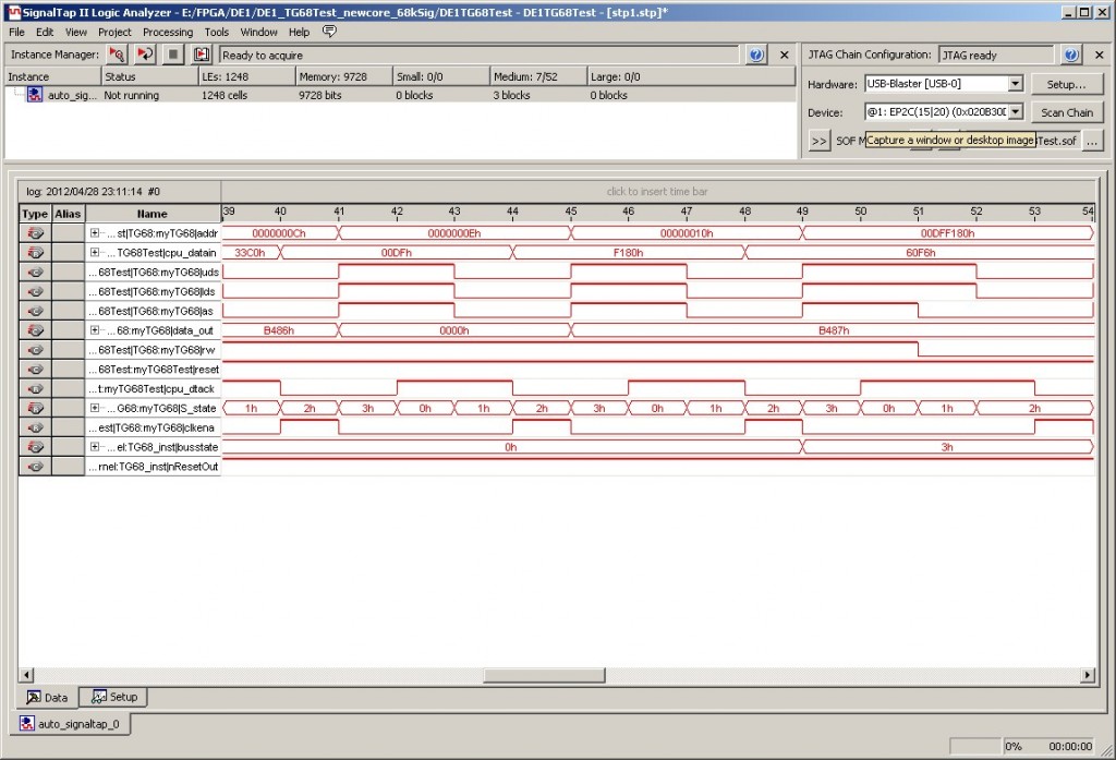
The complete Quartus project can be downloaded here if you’re interested. It runs fast enough that the hex display appears to just read “8888”, but if you press Key0, which acts as a reset button, you can freeze the display and read off the number. Signaltap can be used to get a better look at what’s going on:

