
My Vampire500 board came with “some assembly required” – the FPGA, SDRAM and level translators were all in place, but installing the non-essential stuff – the micro SD slot and PS/2 socket – was left as an exercise for the user!
I want to press the Micro SD slot into service so that I can load alternative Kickstart ROMs, because my old A500 board has kickstart 1.3, and I need a more up-to-date ROM to test Zorro III autoconfig, and to run certain test software.
As it happens I haven’t done any surface mount work before, so I was a bit nervous about attacking an almost-one-of-a-kind board with a soldering iron – but after butchering the control board from a dead hard-drive and convincing myself that I *am* capable of soldering on that scale, I had a go at mounting the micro SD socket. I was relieved to find that it has locating pegs that fit holes in the PCB, so at least I didn’t have to worry about alignment.
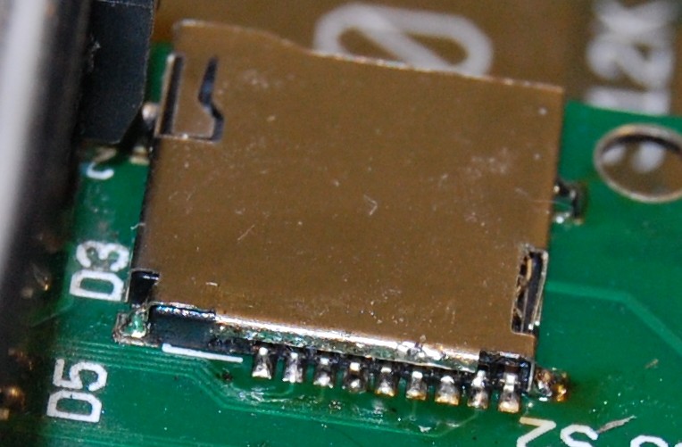
Well it *looks* OK – now to see if it actually works!
Nice 🙂
It was very difficult to design footprint for that specific socket. I don’t know why but many manufacturers decided to develop their own MicroSD socket instead of building one by one standard. I wanted to use this one because it has eject mechanism and in the same time pins for soldering are easy accessible. This is not case in MicroSD sockets used in Nokia phones for example. They are very hard to solder because pins are beneath socket. As you can see all tiny holes on PCB fit and I hope that I solved all voltage needs regarding capacitors and resistor needed for complete operation. I don’t know if it works because I never tested. I only done basic SPI communication but I m worried by one thing that socket is not so close to FPGA so i think that it can’t work on higher freq because clk trace is too long.
Well I won’t have time to test it for a day or two yet – but since the SD card on the top right board here: http://retroramblings.net/?attachment_id=394 works OK, I don’t think trace length will be much of a problem. 🙂