Experimenting with TG68

Part 9 – Accessing the SD card

A computer’s not much use without a way to load data onto it, so the latest aspect of this project has been getting the SD card slot doing something useful.

SD cards have more than one way of accessing them – they have a “native” protocol, and then an SPI mode.  While the native mode can provide better performance, an SPI host is a built-in feature of many microcontrollers, and documentation is easier to come by.  The Minimig project uses the SD card in SPI mode, and since I’m using that project for reference wherever I’m finding gaps in my own understanding, I’ve used SPI as well!

At one time it was nearly impossible for a hobbyist to obtain official SD card specifications – thankfully the situation is much improved now, and a simplified specification is now available for free download at https://www.sdcard.org/downloads/pls/

Another useful page for reference is this: http://elm-chan.org/docs/mmc/mmc_e.html

One thing that confused me to start with is that to invoke “CMD0” we have to send 0x40 to the SD card, while “CMD1” ends up being 0x41, and so on.  This is because the SD native protocol employs a ‘0’ start bit, then a ‘1’ transmission bit – and these are retained even in SPI mode.

Another peculiarity of SPI is that communication is always bidirectional; the host provides 8 clocks, and eight bits of data are sent in each direction.  This means that in order to read responses from the card, the host must write a dummy byte for each byte it wishes to receive.

For the MiniSOC project, I’ve added some extra hardware registers in the peripheral controller at base 0x810000

0x20: SD
   On read, returns the data received during the previous
   write operation.
   On write, causes the byte written to the low 8 bits to be
   clocked out, and data from the card to be clocked in.
   Note: this is asynchronous, so it's important to check that any
   previous write has finished!

0x22 SD_CS
  Read: bit 15 indicates whether the SPI host is busy performing
   a transfer
   Write: bit 0 sets the chip select line of the SD card.

0x24 - SD_Blocking.
   This is equivalent to 0x20 except that both reads and writes will
   incur wait states until any previous transfer has completed,
   eliminating the need to poll 0x22.

0x100 onwards:
   This area is deliberately incompletely decoded, so reads from
   anywhere within the region will have the same effect.  Unlike both
   0x20 and 0x24, reading from these registers will trigger a new
   transfer, sending sixteen bits of 0xffff and receiving 16 bits back
   from the SD card.  The point of this is to allow driver code to use
   constructs like this:

; set up a block read command, then...
  lea 0x810100,a0
  lea sector_buffer,a1
  move.l #15,d7
  move.w (a0),d0 ; pump the first 16 bits.
.loop
  movem.l (a0),d0-6/a2 ; pump 64 bits in one command!
  movem.l d0-6/a2,(a1)
  add.l #32,a1
  dbf d7,.loop

This is much faster than receiving data a single byte at a time.

Full source and binaries can be found here, for anyone that might be interested.

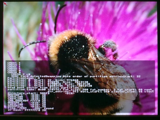
To try this out, you’ll need (a) an Altera DE1 board, (b) HyperTerminal or (preferably) something similar but faster, and (c) an SD card containing the file “Test.img” from the Misc directory in the archive.

Use Quartus to program the DE1 with the .sof file.

Use HyperTerminal or similar at 115200 baud, 8N1, to send the file “out.srec” from the CFirmware directory in the archive.  If everything goes to plan, the MiniSOC should load the image, display it on screen, then scroll up and down as before.

One of the next tasks will be to bootstrap directly from the SD card, eliminating the need for serial bootstrapping.

Experimenting with TG68

Part 8 – Timers and C code

Having successfully uploaded an S-record program over RS232 last time, I’ve since followed the helpful instructions in Christian Vogelgsang’s Chameleon Minimig repo for setting up a cross-compilation toolchain.  I’m now able to build C software for this project, which in the absence of a more imaginative name, I’m coming to think of as “MiniSOC”.

(In fact, I haven’t used newlib – and nor did Christian in the finish – instead we’ve drawn from klibc, just cherry-picking the routines needed for the task at hand.  There are also a couple of other dependencies for building GCC – gmp, mpfr and mpc, which are a stack of libraries for handling multi-precision arithmetic.)

Since I’m not familiar with the syntax used by GCC’s assembler (which is very unlike the “normal” Motorola syntax) I also used VASM to build assembly components to Elf format, then the cross-compiled objdump to create S-records from the final project.

I also used srec_cat, as before, to create .mif files from the lowest-level startup file, which ends up in an M4K.

The biggest change hardware-wise this time round is the addition of some timers.  There are now eight in total, two of which directly divide the system clock, and the other six divide the output of the first timer.  Three of those run in continuous mode, and three run as one-shot timers.

An event on any of those six timers will trigger an interrupt, and the one timer I haven’t yet mentioned will eventually be used to provide an SPI clock when I implement SD card access.

The firmware file CFirmware/out.srec contains basically the same graphics demo as previous builds, implemented in assembler, but with the housekeeping and keyboard/mouse drivers in C.  One of the one-shot timers is used to provide a mouse time-out, so the project will still run even if there’s no mouse connected.

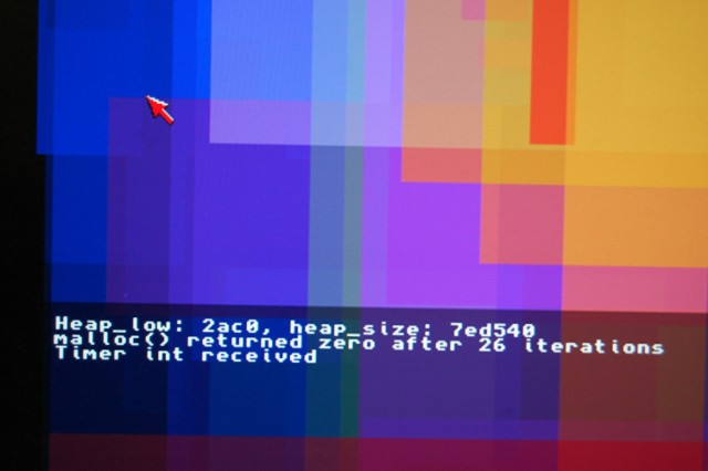
Thanks to code borrowed from klibc, the FrameBuffer’s address is no longer hardcoded, and instead is malloc()ed.  Since there’s no operating system to provide memory blocks to the malloc arena, I’ve added a routine to add a hardcoded block of memory for use by malloc().  The actual bounds of that block are specified by the GCC linker script.  This allows me to hardcode the upper bound to match the hardware, but have the lower bound automatically set immediately above the region occupied by the firmware itself.

This version has a keyboard driver, too – incomplete but functional enough that what you type ends up on screen.  Mouse buttons are also detected, and will cause the colours to cycle more rapidly.

Full source and binaries can be found here.

Baby steps towards AGA support

The current publicly available sources for the Minimig project only support the ECS chipset, there’s not yet any support for AGA.  (The Minimig core used by the FPGA Replay board *does*, apparently, have robust AGA support, but the sources haven’t yet been released to the wider world.)

So I decided to have a go at adding a little AGA functionality myself.

Compared with the ECS chipset, the AGA chipset doesn’t actually add that much complexity.  The extra features are basically:

  • Colourtable extended from 32 entries to 256.  There are still only 32 colourtable registers, and they’re accessed in banks, which are selected in another register.
  • Colourtable entries are now 24-bit deep rather than just 12.  A select bit in another register determines whether colourtable writes go to the most- or least-significant 12 bits.
  • There are now 8 bitplanes instead of 6
  • Bitplane data can be exclusive-ored with a mask value.  This enables some neat tricks with “copper chunky” modes, among other things.
  • Sprites can be high-res
  • Data can now be fetched 32-bits at a time, double-pumped or both, giving an effective 64-bit datapath.

The easiest place to start is the colourtables, which in the present Minimig design are stored in registers.  Since the colourtable was about to balloon from 32 12-bit entries to 256 24-bit entries, I migrated the colourtable to a pair of M4Ks – one to take the upper 12-bits of each colour, the other to take the lower 12-bits.

I also implemented enough of the BPLCON3 and BPLCON4 registers to support colourtable bank selection and masking.

I’ve also created a small Copperlist demo in ADF format for testing, which can be found here.

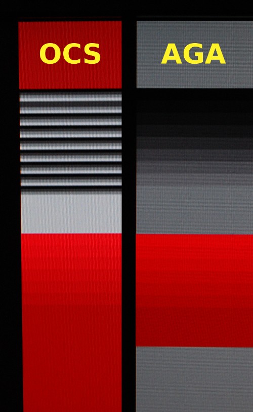
This demo simply uses lower-bit entries and palette masking as a test – the following screenshot shows how it looks under ECS and under AGA.

(Note that while the colourtable entries store 24-bits, they’re still only displayed as 12-bit, because that’s all the DE1 Board’s VGA output can handle without extra dithering, which will come later.)

A git repo containing the current code is here, while a binary can be found here.

Please note that this is highly experimental – there are timing inaccuracies compared with the real chipset, extra-half-brite mode is currently broken. (and the normal Minimig boot text is missing as a result of another experiment to reduce the size of the boot ROM!)