Reading a Sega 6-button pad

Part 4: Up and running

I’m pleased to report that the first prototype of the PSOC4-based Sega 6-button pad to Amiga CD32 adapter is now up and running.  In the process I’ve learned a lot about the PSOC4 platform, and I have to say as a development platform I really like it – I have no doubt I shall be using these devices in future projects.

PSOC Creator Project files for the adapter can be found at https://github.com/robinsonb5/SegaToCD32

Reading a Sega 6-button pad

Part 2: some code

In my earlier post I mentioned that I was going to handle reading the Sega 6-button joypad in software, using an interrupt routine, and use programmable logic to handle masquerading as a CD32 pad.

The six inputs from the Sega pad (up, down, left, right, button1, button2) are mapped to PSOC pins P2.0 to P2.5.  Since these are adjacent, we can read and write to them easily as a single entity.  We create a “pins” component with six inputs, named Sega_Inputs, and PSOC creator automatically generate headers and stubs so that we can read their status in main.c simply by calling Sega_Inputs_Read().  Similarly, we create an output pin, Sega_Select on pin P2.6, which we can write in the code using Sega_Select_Write().

Continue reading

Reading a Sega 6-button pad

Part 1: The Plan

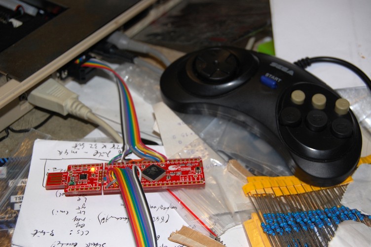
One of the projects I have in mind for the PSOC4 chip on the CY8CKIT-049-42xx boards I picked up recently is an adapter to allow 6-button Sega Megadrive controllers to be used on the Amiga.  I already made such a device a couple of years ago using a PIC microcontroller but never finished the project (I discovered FPGAs round about then!) and the programmable digital blocks in the PSOC4 make it an ideal platform for resurrecting the project.

Initially I shall read the Sega pad in software, using an interrupt routine, then implement the CD32-pad shift register using the programmable hardware in the PSOC4.

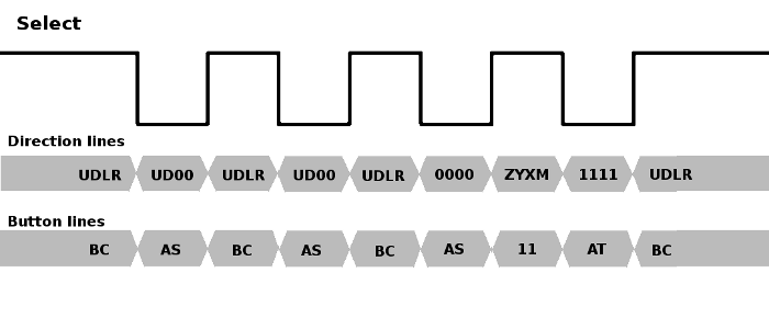
The original Sega Megadrive gamepad had four buttons: A, B, C and Start.  The pad used a standard Atari-style 9-pin DSUB connector, and while the four directions and button B were mapped using standard Atari wiring (pins 1,2,3,4,6), button C appeared on pin 9.  Most Atari-like gameport connectors have +5v available on pin 7, but the Sega variant has +5v on pin 5.  Instead, pin 7 is used as a select signal, which multiplexes the pins normally occupied by the B and C buttons.  When the select signal is high, B & C are readable, and when the select signal is low, the status of buttons A and Start appear on those lines instead.

When it came to adding extra buttons to the six button pad, Sega needed to find a way of multiplexing extra buttons in such a way that they didn’t cause compatibility issues.  The obvious solution of making extra buttons replace the direction lines when the select signal is low wasn’t possible because the existing 3-button protocol already held the left and right lines low when select was low, presumably so software could distinguish the 3-button pad from a standard Atari-style joystick or Master System controller.  Instead they went with a “magic knock” approach, in which software toggles the select line four times in quick succession.  The new buttons appear on the directions during the high pulse following the third low pulse, and to identify the pad as a six button button, the direction lines are low and high for the low pulses before and after this, respectively.

SegaPad

Configuring ZPUFlex

In the few months since I started playing around with the zpu_small core, expanding it into what ultimately became ZPUFlex, my variant of the CPU has gone from being an interesting experiment to something that might actually see some usefulness in other projects.

ZPUFlex was intended from the outset to be configurable and flexible, but this comes at the cost of complexity, and there are a number of competing factors to consider when configuring the CPU.  The following is an attempt to document some of the choices that must be made when using ZPUFlex.

Continue reading

PSOC4 – another distraction!

I have a new toy to distract me from my existing projects!

I recently came across this neat little prototyping kit from Cypress Semiconductor, and several aspects of the device piqued my interest:

  • The cost is low enough that you don’t have to think twice about using one in a project
  • The chip has an ARM Cortex M0 CPU core
  • The 42xx version (as opposed to the 41xx version) has a small amount of FPGA-like programmable logic built in
  • The device is programmed via an onboard USB/TTL converter, which in a piece of superbly elegant design can be “snapped off” the board once programming is complete.
  • The device is capable of running from 5v, and handling 5v signals. Continue reading

Nostalgia trip du jour

If you miss the days of there being half a dozen different Amiga magazines to choose from on the news-stands, then Mark Stanner’s on-line publication “880 Gamer” might make you smile!  The PDF publication has a range of game reviews, a number of adverts from back in the day, reviews of a few scene demos, and even a letters page!  If you miss the days of covermounted floppy disks, you won’t be disappointed, either, since there’s a cover disk in .adz format!

Issue 3 is out now, and can be found here: http://www.users.on.net/~stanners/

issue3

Experimenting with TG68

Part 14: Improving the SDRAM controller

One limitation of the MiniSOC project so far has been that only a very basic 16-bit 640×480@60Hz screenmode is supported.  The reason for this is mainly RAM bandwidth, since the boards I’m targetting have single-data-rate SDRAM.

The SDRAM controller I’m using is derived from the one Tobias Gubener created for the TG68-based versions of the Minimig core.  The original controller used 4-word bursts when reading from SDRAM, wrote in single words, and operated on a fixed 16-clock cycle, which had the advantage of guaranteeing a deterministic response time for the Amiga emulation. Continue reading

Gotek Floppy Emulator Revisited

The circuit I cobbled together a few weeks ago to add sound support to the Gotek floppy emulator worked up to a point, but it was ugly as hell, and suffered from occasional stray oscillations.  H.M. – the mastermind behind the new Amiga-compatible firmware for the Gotek unit – suggested using a MOSFET instead of the BJTs, and since I’m still shaky on the use of transistors it seemed like a good opportunity to learn.

Continue reading