Well that was nerve-wracking!

My Vampire500 board came with “some assembly required” – the FPGA, SDRAM and level translators were all in place, but installing the non-essential stuff – the micro SD slot and PS/2 socket – was left as an exercise for the user!

I want to press the Micro SD slot into service so that I can load alternative Kickstart ROMs, because my old A500 board has kickstart 1.3, and I need a more up-to-date ROM to test Zorro III autoconfig, and to run certain test software.

As it happens I haven’t done any surface mount work before, so I was a bit nervous about attacking an almost-one-of-a-kind board with a soldering iron – but after butchering the control board from a dead hard-drive and convincing myself that I *am* capable of soldering on that scale, I had a go at mounting the micro SD socket.  I was relieved to find that it has locating pegs that fit holes in the PCB, so at least I didn’t have to worry about alignment.

MicroSD

Well it *looks* OK – now to see if it actually works!


It’s Aliiiiive!

After spending a satisfying few hours tracking down a stubborn bug which turned out to be a mere bad solder joint, my old A500 motherboard is now able to boot using the Vampire500 board in place of the CPU!

FirstBoot

Unfortunately, since that means I can now play some old favourites on the board (in the name of testing, of course!) there probably won’t be much more progress today!

Pang

From the “What, are you nuts?” department!

I have an Amiga with a ZPU processor!

So what possessed me to create such a perverse combination? Quite simply that it synthesizes in about a third of the time that a TG68-based equivalent would, which speeds up the development cycle significantly while I’m bug hunting.

(I will admit there’s an element of “because I can” there, too!)

ZPUChipRAMTest

This not-very-exciting screenshot shows a simple program running on the ZPU, and testing the reliability of reads and writes to Chip RAM through the Vampire500.  The program simply sets up a 2-colour high-res screen, clears the framebuffer, and then repeatedly adds 1 to each longword within the framebuffer.  Any glitches in either reading or writing would thus be cumulative, so if I can leave the program running for a while and if the pattern on screen remains in nice neat columns (which it does), I can be sure that no glitches have occurred. (Or that any errors are perfectly consistent!)

Of course, a ZPU-based Amiga is of no practical use whatsoever, besides assisting in debugging the Vampire500 – but I find myself idly wondering how practical it would be to use a more modern CPU – such as, perhaps, the OR1200 – and then emulate the 68000 in firmware?

Anyhow, pipe-dreams aside, the next task will be to take a checksum of the Kickstart ROM, since ROM reads are the only kind I haven’t yet tested.

A New Distraction!

I have another new toy to distract me from all the things I should be doing!

Vampire500_InSitu

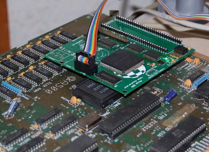
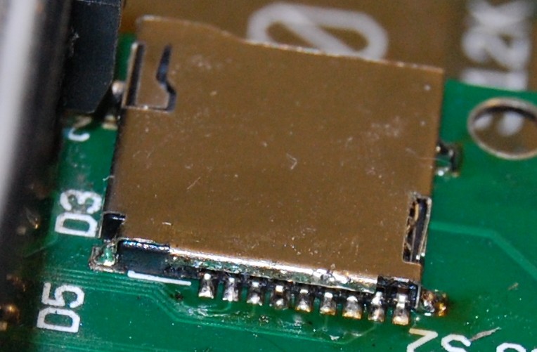
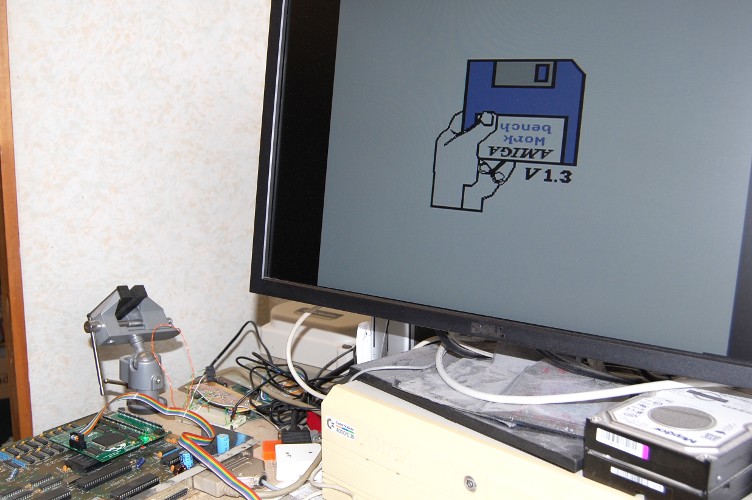
This is one of Majsta’s hand-assembled prototypes of his FPGA accelerator, connected to a spare A500 motherboard that I just happened to have lying around.  (I don’t currently have an A600 to play with, which is why Majsta sent me the less-mature A500 variant of the project).  While I’ve been trying to help with the SDRAM problems his project’s run into, there’s only so much I can do without access to the hardware.  Well, now I have that access!

The A500 variant of the project’s not yet as complete as the A600 version, and can’t yet boot from the TG68 processor, so now begins the fun of testing the various kinds of accesses to the A500 motherboard, and ironing out the glitches.

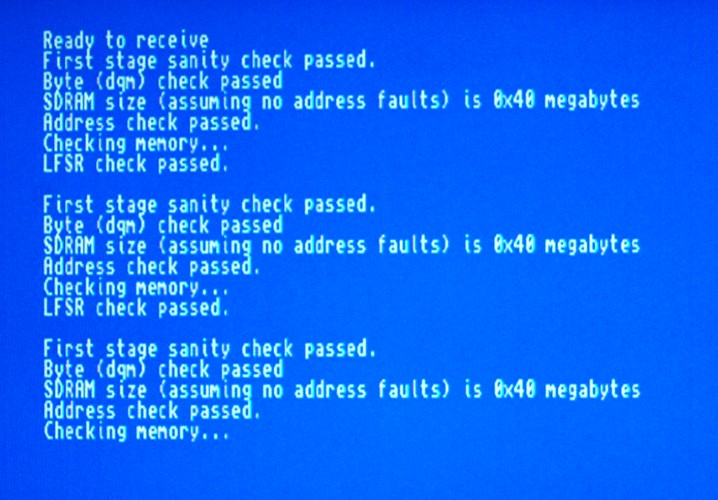
Because the whole project takes some time to build, while I’m testing and diagnosing I’m using a simple state machine to simulate the CPU, which looks like this:

library ieee;
use ieee.std_logic_1164.all;
use ieee.std_logic_unsigned.all;
use ieee.numeric_std.all;

entity DummyCPU is
    generic(
        SR_Read : integer:= 0;         --0=>user,   1=>privileged,      2=>switchable with CPU(0)
        VBR_Stackframe : integer:= 0;  --0=>no,     1=>yes/extended,    2=>switchable with CPU(0)
        extAddr_Mode : integer:= 0;    --0=>no,     1=>yes,    2=>switchable with CPU(1)
        MUL_Mode : integer := 0;       --0=>16Bit,  1=>32Bit,  2=>switchable with CPU(1),  3=>no MUL,  
        DIV_Mode : integer := 0;       --0=>16Bit,  1=>32Bit,  2=>switchable with CPU(1),  3=>no DIV,  
        BitField : integer := 0           --0=>no,     1=>yes,    2=>switchable with CPU(1)  
        );
   port(clk                   : in std_logic;
        nReset                 : in std_logic;            --low active
        clkena_in             : in std_logic:='1';
        data_in              : in std_logic_vector(15 downto 0);
        IPL                      : in std_logic_vector(2 downto 0):="111";
        IPL_autovector       : in std_logic:='0';
        CPU                 : in std_logic_vector(1 downto 0):="00";  -- 00->68000  01->68010  11->68020(only some parts - yet)
        addr                   : buffer std_logic_vector(31 downto 0);
        data_write            : out std_logic_vector(15 downto 0);
        nWr                      : out std_logic;
        nUDS, nLDS              : out std_logic;
        busstate                : out std_logic_vector(1 downto 0);    -- 00-> fetch code 10->read data 11->write data 01->no memaccess
        nResetOut              : out std_logic;
        FC                  : out std_logic_vector(2 downto 0);
-- for debug        
        skipFetch              : out std_logic;
        regin                  : buffer std_logic_vector(31 downto 0)
        );
end DummyCPU;

architecture rtl of DummyCPU is

type states is (write1,write2,write3,write4,write5,write6,read1,read2);
signal state : states := read1;
signal counter : unsigned(15 downto 0);
signal temp : std_logic_vector(15 downto 0);

begin

process(clk)
begin
    nResetOut<=nReset;
    if nReset='0' then
        state<=read1;
    elsif rising_edge(clk) then

        case state is

            when write1 =>
                data_write<=temp; -- std_logic_vector(counter);
                addr<=X"00DFF180";
                busstate<="11";    -- Write data
                state<=write2;
                nWR<='0';
                nUDS<='0';
                nLDS<='0';

            when write2 =>
                if clkena_in='1' then
                    state<=write3;
                end if;

            when write3 =>
                addr<=X"00BFE201";
                data_write<=X"0003"; -- Set OVL and LED as output
                nWR<='0';
                nUDS<='1';
                nLDS<='0';    -- Byte write to odd address.
                state<=write4;

            when write4 =>
                if clkena_in='1' then
                    state<=write5;
                end if;

            when write5 =>
                addr<=X"00BFE001";
                data_write<=X"FFFF";
                data_write(1)<=temp(6);    -- Echo mouse button status to keyboard LED.
                nWR<='0';
                nUDS<='1';
                nLDS<='0';    -- Byte write to odd address.
                state<=write6;

            when write6 =>
                if clkena_in='1' then
                    state<=read1;
                end if;

                when read1 =>
                addr<=X"00BFE001";
                busstate<="10";    -- Read data
                state<=read2;
                nWR<='1';
                nUDS<='1';    -- Byte read from odd address.
                nLDS<='0';

            when read2 =>
                temp<=data_in;
                if clkena_in='1' then
                    state<=write1;
                end if;

        end case;
    end if;
end process;

end architecture;

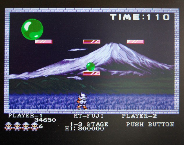
This state machine reads the value of CIA-A PRA and writes the value read to the COLOR0 register, so the colour of the screen changes in response to the mouse or joystick buttons. It also writes the status of the left mouse button to the LED bit, so the keyboard LED lights in response to the mouse button.

Next I shall test reads and writes to Chip RAM and reads from the Kickstart ROM for reliability.

Caching and Bus Snooping

When I first added the Turbo ChipRAM feature to the Minimig core, there were suprisingly few unpleasant side-effects. However, one side-effect did become apparent when I added the Two-way CPU cache.

On a real Amiga, it’s possible for the CPU’s bus and the chipset’s bus to operate independently, so if Fast RAM is available, the CPU can conduct a FastRAM operation at the same time as the chipset is reading or writing from Chip RAM. On the TG68-based Minimig variants, there’s only one type of RAM available – SDRAM, and no matter how they’re handled, Chip RAM and Fast RAM accesses ultimately all end up in the same RAM chip. Chip RAM accesses are coordinated by the Minimig’s chipset emulation, while Fast RAM accesses use a different port in the SDRAM controller and bypass the Minimig chipset emulation entirely, which is much faster. This is the key to my “Turbo ChipRAM” option – which basically allows Chip RAM to be accessed through the SDRAM controller’s Fast RAM port.

The problem is that the Fast RAM port is cached, so if the chipset writes to a piece of Chip RAM which happens to be in the cache, the cached data becomes stale, and next time the CPU reads that address it received the stale data, not the newly-written data.

The solution to this is to perform Bus Snooping. The CPU cache needs to monitor the SDRAM controller’s Chip RAM port, watching for writes, and any time it sees a write to an address that’s in cache, it must either update or flush the cached data.

I’ve taken the easier but slower option here, simply marking the data as invalid, forcing it to be re-read from SDRAM next time the CPU wants to access it. There’s scope to improve performance by updating the cached data and leaving it marked as valid. The cost for this would simply be the extra logic elements needed to store the written data temporarily and write it to the cache.

Source for the Two-way cache with Bus Snooping can be found here – and I’ll try and release a new version of the Chamemleon core in the near future with this change included.

ProjectXG Redux

Anyone remember CU Amiga Magazine’s “ProjectXG”?  This was a DIY project they ran, based on a hack that was published on Aminet, to interface a Waveblaster MIDI daughterboard to the Amiga’s serial port, to provide a pretty good quality MIDI tone module.

The daughterboard most commonly used for this project was Yamaha’s DB50XG, though any card which attached to a “Waveblaster” header could be used.  (Googling Waveblaster now, however, will find you a Yamaha product of quite a different nature.)

The DB50XG’s successor, the DB60XG was manufactured under license by NEC as the XR385, and this seems to be the easiest such card to find these days.  It’s very similar to the DB50XG, it just has some very subtly different voicing, and can apply its DSP effects to incoming audio as well as its own sounds.

Having built a ProjectXG many years ago, then selling it a year or so back and promptly building another one, I naturally wanted to interface a Waveblaster card to one of my Minimig variants, and listen to some old MIDI files again.
Continue reading

Digging up old projects: FreeWheel

I received an email a few days ago asking whether I still support the FreeWheel utility. This is something I wrote back in the mists of time to provide mouse wheel support for the Amiga. It wasn’t a mouse driver as such, instead it set up an input handler that watched for “Newmouse” events, and attempted to translate them into keypresses or slider nudges, or whatever was appropriate for the window currently under the cursor.

The other nice thing FreeWheel could do was to adjust the mouse speed in very fine increments. Instead of merely multiplying mouse movements by an integer constant, it multiplied by a fractional amount, and maintained a remainder, so if you wanted your mouse to be 23% faster, FreeWheel could oblige.

The requested change was simply to provide a 68000-compatible build, since the build on Aminet was for 68020+ only, and as it happens this was a really easy request to fulfil, so… some 14 years after the first release on Aminet, a new build is now available!
http://aminet.net/util/mouse/FreeWheel.lha

Trials, Tribulations and Toolchains

Edit: Future me, nearly 10 years later, says don’t bother attempting these steps unless you really have no alternative. My comment below about guides found on the net quickly becoming obsolete now applies to this post!

If you’re using Ubuntu or a derivative, then the arm-none-eabi-… toolchain is now in the repos, so can easily be installed with apt, and there’s even an m68k gcc cross compiler too.

<Historical content resumes…>

To build the OSD firmware for the Minimig projects, a cross-compilation environment is needed. Configuring GCC for this task can be an arcane process, and aspects tend to change from time to time, so guides found on the net quickly become obsolete. For instance, guides recommending the target “arm-elf” will fail with the latest GCC. Instead we need to use the target “arm-none-eabi”.

Here’s how I built a toolchain for building both M68K (Chameleon Minimig port) and ARM (Original Minimig and MiST) versions of the firmware:
Continue reading