Part 3 – Hello World!
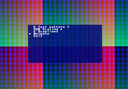
This time round I’ve added the On-screen Display component, and the firmware verifies that it’s working correctly by way of the archetypal “Hello World!” message!
I’ve also added project files for the MIST board, and will add support for a Xilinx-based board in the near future.
The source tree to accompany this part is tagged in the git repo as Step2.
The OSD component itself provides a few hardware registers that can be accessed from software, along with a 512-byte character buffer.
The VHDL interface looks like this:
entity OnScreenDisplay is
port(
	reset_n : in std_logic;
	clk : in std_logic;
	-- Video
	hsync_n : in std_logic;   -- Sync inputs from the main core, used to time the
	vsync_n : in std_logic;   -- window and pixel signals and position the OSD.
	enabled : out std_logic;
	pixel : out std_logic;
	window : out std_logic;
	-- Registers
	addr : in std_logic_vector(8 downto 0);
	data_in : in std_logic_vector(15 downto 0);
	data_out : out std_logic_vector(15 downto 0);
	reg_wr : in std_logic;
	char_wr : in std_logic;
	char_q : out std_logic_vector(7 downto 0)
);
end entity;
The readable registers are implemented using simple combinational logic and will thus respond within a single clock, so we don’t bother with any kind of req / ack mechanism here, in the interests of keeping things simple.
Address and data from the CPU are placed on addr and data_in, and reg_wr is brought high to trigger a write to a register, and a char_wr is brought high to trigger a write to the character RAM.
data_out and char_q will output data from registers and character RAM, respectively, based on the addr input. This is a constant connection – no req signal is needed. If reading from the registers triggered some kind of action then we’d need a more complete req/ack mechanism here, but since reads are completely passive we don’t need to worry about it in this case.
Continue reading →


