Experimenting with TG68

Part 1: a counter

The TG68 softcore processor is an MC68000-compatible processor core written by Tobias Gubener, and used in the DE1, DE2 and Turbo Chameleon 64 ports of the Minimig project.  The latest version of the core also supports most 68020 instructions,making it a pretty powerful and useful general purpose processor for FPGA applications.

As a learning exercise I wanted to try using the TG68 in a minimal project – a first step towards the “build-my-own-computer” dream I alluded to in an earlier post.

The TG68 consists of two layers – there’s the processor core itself which has a pretty simple interface, then there’s a wrapper which makes it largely signal-compatible with a “real” 68k processor.  For this project I’ve used the wrapper – but later projects will show how the processor can be used “bare”.

To test the processor, I’ve created a very simple program, assembled with Easy68k.

ORG    $0000
    dc.l      $0      ; Initial Stack Pointer
    dc.l      $8      ; Initial Program Counter
START:                ; first instruction of program
    addq.w    #1,d0
    move.w    d0,$dff180
    bra.s    START

    END    START        ; last line of source

This program runs in a loop which increases register D0 by 1 each iteration, and writes the new value to location $dff180.  (This is the location of the background colour register in the Amiga’s custom chipset – so this program, running on an Amiga, would result in a colourful flickering screen, similar to many decrunchers back in the day.)

The minimal program above assembles to a mere 5 words:

$08: $5240
$0A: $33C0
$0C: $00DF
$0E: $F180
$10: $60F6

(Note that the longword at location 0 is the initial Stack Pointer, and at location 4 is the initial Program Counter, so we start the actual program at location 8.)

In the interests of getting the processor up and running with as little effort at possible, I’ve not attempted to run the program from RAM – instead I decode the appropriate addresses directly in VHDL, like so:

process(clk,cpu_addr)
begin
    if rising_edge(clk) then
        if cpu_as='0' then    -- The CPU has asserted Address Strobe, so decode the address...
            case cpu_addr(23 downto 0) is
                -- We have a simple program encoded into five words here...
                when X"000006" =>
                    cpu_datain <= X"0008"; -- Initial program counter.  Initial stack pointer and high word of PC are zero.
                    cpu_dtack<='0';    
                when X"000008" =>
                    cpu_datain <= X"5240";  -- start: addq.w #1,d0
                    cpu_dtack<='0';    
                when X"00000A" =>
                    cpu_datain <= X"33c0";  -- move.w d0...
                    cpu_dtack<='0';
                when X"00000C" =>
                    cpu_datain <= X"00DF";  -- ...
                    cpu_dtack<='0';    
                when X"00000E" =>
                    cpu_datain <= X"F180";  -- ...,$dff180
                    cpu_dtack<='0';    
                when X"000010" =>
                    cpu_datain <= X"60f6";  -- bra.s start
                    cpu_dtack<='0';

                -- Now a simple hardware register at 0xdff180, written to by the program:
                when X"dff180" =>
                    if cpu_r_w='0' and cpu_uds='0' and cpu_lds='0' then    -- write cycle to the complete word...
                        counter<=cpu_dataout;
                        cpu_dtack<='0';
                    end if;

                -- For any other address we simply return zero.
                when others =>
                    cpu_datain <= X"0000";
                    cpu_dtack<='0';
            end case;
        end if;

        -- When the CPU releases Data Strobe we release dtack.
        -- (No real need to do this, provided everything responds in a single cycle.  DTACK Grounded!)
        if cpu_uds='1' and cpu_lds='1' then
            cpu_dtack<='1';
        end if;
    end if;
end process;

When the processor writes to $dff180, the VHDL snippet above captures the value written, and in the full project writes it to the Hex display on the DE1 board.

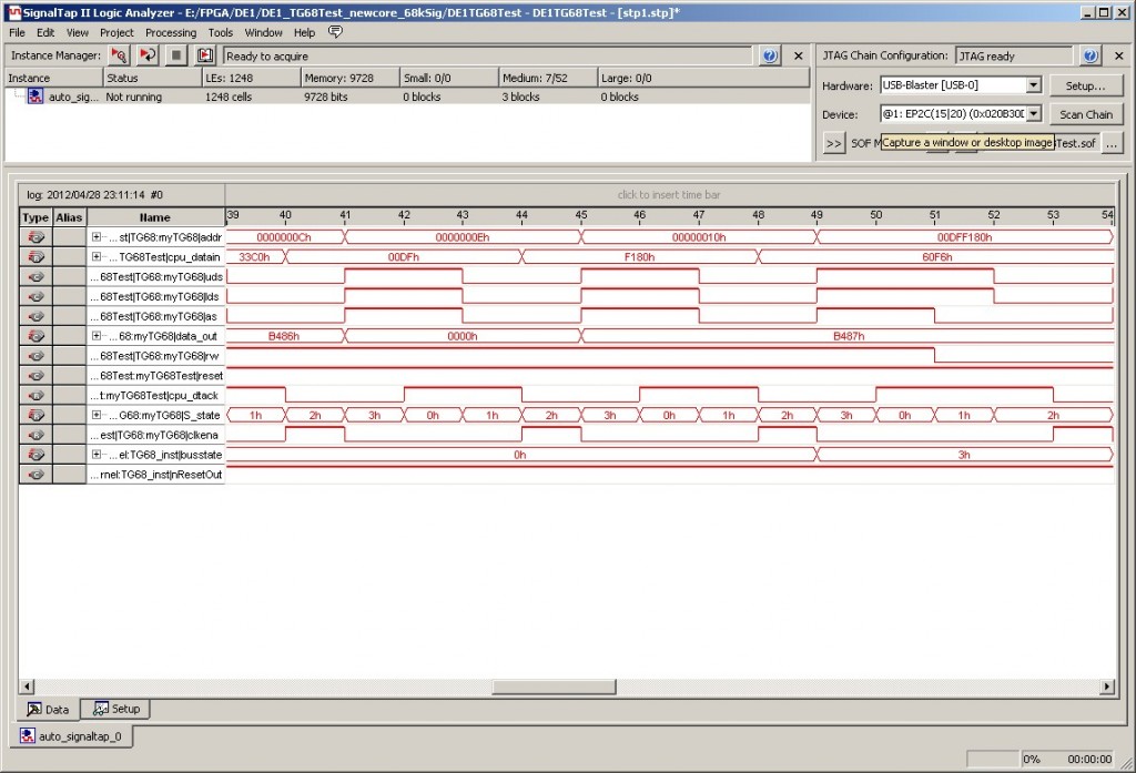
The complete Quartus project can be downloaded here if you’re interested.  It runs fast enough that the hex display appears to just read “8888”, but if you press Key0, which acts as a reset button, you can freeze the display and read off the number.  Signaltap can be used to get a better look at what’s going on:

Minimig on the DE1 dev board

In my previous post I talked about FPGAs and the Minimig project.  One of the platforms that has received a port of Minimig is the Altera/Terasic DE1 FPGA development board.  This is a nice little board which comes with a Cyclone 2 FPGA, 8 meg of SDRAM, some SRAM, some flash and a controller chip to configure the FPGA at power-on.  It also has an SD card slot, PS/2 keyboard port, VGA out, an RS232 serial port, an audio codec, some switches, LEDs and a couple of 40-pin general purpose IO headers.

The one downside to this board is that the FPGA is a bit poky, with only about 20,000 logic elements – only just enough to hold the Minimig design, and not large enough to hold the latest 68020 version of the TG68 softcore.

The original DE1 port of Minimig can be found here, while a fork which will hopefully see some new developments in the future can be found here.  Binaries are available, and also complete source if anyone’s else is interested in playing with it.

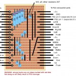
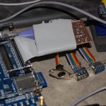
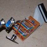
While the DE1 board has a PS/2 keyboard port, there’s no mouse port and (unsurprisingly!) no DB9 joystick ports – so these need to be added via an extra board connected to one of the GPIO headers.  The source archives contain a suitable schematic, but since my circuit creation skills don’t yet extend beyond stripboard, I made a stripboard layout for the extra board. The layout and a couple of photos of the completed board appear below:

Of Amigas and FPGAs

As a teenaged computer geek in the early 90s my dream was (of course!) one day to build my own computer.  Fast forward a couple of decades, and there are now various ways in which nostalgic geeks like myself can actually fulfil this dream.  One option is the Fignition which is easy enough to build that a suitably-enterprising child can do it!

For someone more used to wielding a compiler than a soldering iron, however, another interesting option is an FPGA development board.  (For the unitiated, an FPGA, or Field Programmable Gate Array, is a logic chip that contains thousands of logic elements whose functions are set at runtime, rather than in the factory.)

Around 2005 there was ongoing discussion in the Amiga community about whether it was possible to implement a replica of the Amiga’s custom chipset in an FPGA.  Dutch electrical engineer Dennis van Weeren answered that question by embarking upon the Minimig project, which since then has evolved into an almost perfect re-implementation of the Amiga 500’s custom chipset.

The classic Minimig board contains a Xilinx FPGA providing the custom chip functions, but contains a real 68000-variant processor.  However, the chipset sources have been ported to other devices, too – most notably Tobias Gubener’s ports to the Altera DE1 and DE2 dev boards, and to the Turbo Chameleon 64.  All three of these ports make use of Tobias’s TG68 “softcore” processor, which is a 68000-compatible processor built from logic elements within the FPGA!

Since all the FPGA projects I’ve mentioned so far are open-source, they provide a valuable library of source material for anyone wanting to experiment with FPGAs, and in the coming posts I will document my own experiments in case anyone finds them interesting, or useful starting points for their own endeavours.

Digging up old projects: AMRWolf

While digging through my old Amiga stuff recently I came across the work-in-progress of AMRWolf, a Wolfenstein3D-style raycasting engine I worked on a long time ago.  it was written in a combination of AMOSPro and assembly language, with the assembly routines inserted into AMOS procedures.

The display was a “Copper Chunky” screen, which gives a low-resolution 128 x 53 pixel 12-bit true-colour display, but has the advantage of being very fast.

I uploaded an early version to Aminet many years ago, but the project did progress a little further since then, before I dropped it and moved onto other things.

Compared with the original demo released in 1996, this version has a couple of extra levels, a map editor and comes with full source.  (Note, however, that the source is not well organised, and I’ve completely lost track of which assembly routine goes in which procedure, so if anyone wants to hack on this, it’s going to be a bit of a puzzle!)

In order to run the game from Within AMOSPro, you’ll need the GameSupport extension in slot 23, which is mentioned in another post, and can also be found on Aminet under /dev/amos.

Download: Latest version of AMRWolf, with complete source and map editor.

Digging up old projects: GameSupport

GameSupport is an AMOSPro extension I wrote in the dim and distant past to make my life easier when writing AMRWolf and the first prototype of AMRVoxel.  Since I’m about to release the final work-in-progress of AMRWolf with source, I’m releasing the extension too.   (The extension occupies slot 23.  Full source is included)

The interesting functions are Gsiconify(), the GsCodeModule concept (maybe I’ll find some example code modules to upload soon) and the GsTrack protracker playroutine, which supports getting command 8 triggers into the program, and also playing a subsection of a module as a “jingle”. (Think Pinball games, where a single pattern plays in a loop until you launch the ball…)

Download: GameSupport extension

Tricks with HAM images

Back in 1985 when the Amiga was first released, the HAM (Hold And Modify) screenmode was revolutionary. It allowed 4096 colours to be displayed simultaneously, meaning near true-colour images could be displayed while only using the amount of memory that a normal 64-colour screen would use.

HAM does have its disadvantages, though – while a regular bitplane image can be faded out very easily by simply fading the palette, this trick doesn’t work for HAM images.

Fading out a HAM image can be done, however, using the Blitter.

This AMOSPro program uses some “evil” trickery to fade a HAM image to black, using the Screen Copy command with blitter modes, peeks and pokes to shuffle bitplanes around between screens, and what amounts to a ShadeBOB routine over the entire screen.

Step by step, the theory of operation is something like this:

  • Logical OR the two control planes together to make a mask plane.  This mask plane is “0” wherever pixels use the base palette, and “1” wherever a direct R, G or B level is being specified.
  • Use the mask plane to perform binary subtraction on the four data planes, using another spare plane to hold carry data.
  • Check for overflow, and zero the image wherever overflow has occurred.

This is done simultaneously with fading out the palette, and the end result is quite a nice fade-out of a HAM image.

Download: Compiled HAM fading slideshow, including AMOSPro source code

A new retro-computing blog is born!

Welcome to Retro Ramblings, my new retro-computing blog.  This site will serve as an outlet for some old Amiga projects that I uncovered recently after digging out my old machines.  I’ll also post here regarding projects tangentially related, such as FPGA development and the Minimig, C64 and suchlike.

I hope as the site develops you’ll find something of interest!