880 Gamer issue 5 is out!

Always worth a plug, 880 Gamer is a magazine produced in the style of the half-a-dozen or so glossy news-stand magazines we could choose from back in the Amiga’s heyday.

Distributed as a PDF, it also has two coverdisks in .adf format, and printable labels for each, should you wish to write them to physical disks!

All five issues of 880 gamer produced to date can be found at: http://www.users.on.net/~stanners/
issue5

A closer look at the OSD/Control Module

Part 5 – Adding a Menu

Having talked in depth about the hardware in previous parts, in this part I’m going to talk about the software side of things.

I mentioned before that the character ROM contains 128 characters which, from characters 32 upwards, are standard 7-bit ASCII. I’ve added some special characters in the lower 32 character slots, however, which have uses in drawing the OSD. The extra characters are as follows:

  • 0 – 7: solid blocks 7 pixels high, 1 to 8 pixels wide, left aligned in the character cells. Useful for drawing progress bars.
  • 8 – 15: As above but right-aligned within the character cell. May be useful in progress bar applications but I haven’t actually used these yet, so might eventually reassign them.
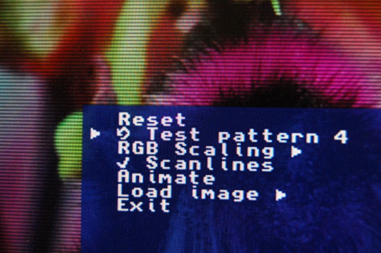
  • 16 – 19: Arrow heads, pointing right, left, up and down, respectively. (The right arrow is used as a cursor in the menu.)
  • 20: Checkmark
  • 21: Cross
  • 22: Cycle
  • 23: ellipsis
  • 24 – 31: Currently unused

For the OneChipMSX and FPGA PC Engine cores I put together a simple, lightweight data-driven menu system, which can be found in CtrlModule/Firmware/menu.[c|h]

OSDMenu

Continue reading

A closer look at the OSD/Control Module

Part 4 – Keyboard control

So far we have the control module printing a message to the screen and autonomously sending signals to the underlying core. Now it’s time to make it somewhat interactive!

To do this we need to add Keyboard support. Many FPGA platforms still have support for PS/2 keyboards simply because they’re electrically simple and don’t require much in the way of high speed transceivers or carefully-routed circuits to drive them. Thus the PS/2 keyboard is a de-facto standard for FPGA projects, even to the point that on the MIST platform (which has no PS/2 ports, but does have USB ports) there is a bridge component available which makes the keyboard masquerade as PS/2. This is taken care of in the MIST-specific toplevel file, which allows the main project files to be identical between platforms.

To add keyboard support we need three things: a hardware interface to the PS/2 socket (whether it’s real or emulated!), software to drive that hardware interface, and support for interrupts, so that the CPU doesn’t have to poll the hardware waiting for keystrokes.
Continue reading

A closer look at the OSD/Control Module

Part 3 – Hello World!

This time round I’ve added the On-screen Display component, and the firmware verifies that it’s working correctly by way of the archetypal “Hello World!” message!
I’ve also added project files for the MIST board, and will add support for a Xilinx-based board in the near future.
The source tree to accompany this part is tagged in the git repo as Step2.

The OSD component itself provides a few hardware registers that can be accessed from software, along with a 512-byte character buffer.

The VHDL interface looks like this:

entity OnScreenDisplay is
port(
	reset_n : in std_logic;
	clk : in std_logic;
	-- Video
	hsync_n : in std_logic;   -- Sync inputs from the main core, used to time the 
	vsync_n : in std_logic;   -- window and pixel signals and position the OSD.
	enabled : out std_logic;
	pixel : out std_logic;
	window : out std_logic;
	-- Registers
	addr : in std_logic_vector(8 downto 0);
	data_in : in std_logic_vector(15 downto 0);
	data_out : out std_logic_vector(15 downto 0);
	reg_wr : in std_logic;
	char_wr : in std_logic;
	char_q : out std_logic_vector(7 downto 0)
);
end entity;

The readable registers are implemented using simple combinational logic and will thus respond within a single clock, so we don’t bother with any kind of req / ack mechanism here, in the interests of keeping things simple.
Address and data from the CPU are placed on addr and data_in, and reg_wr is brought high to trigger a write to a register, and a char_wr is brought high to trigger a write to the character RAM.
data_out and char_q will output data from registers and character RAM, respectively, based on the addr input. This is a constant connection – no req signal is needed. If reading from the registers triggered some kind of action then we’d need a more complete req/ack mechanism here, but since reads are completely passive we don’t need to worry about it in this case.
Continue reading

A closer look at the OSD/Control Module

Part 2 – a simple test core

To demonstrate how the control module is built, we need a core to which we can add the control module.  In the interests of keeping the project as simple as possible and avoiding needless distractions, I’ve started a new project for this purpose, which can be found on github at https://github.com/robinsonb5/CtrlModuleTutorial

I shall tag this at key points, and at the time of writing there are two tags in place.
To play with this, check out a local copy of the core, like so:

> git clone https://github.com/robinsonb5/CtrlModuleTutorial.git
> cd CtrlModuleTutorial
> git submodule init
> git submodule update
> git checkout <tag name>

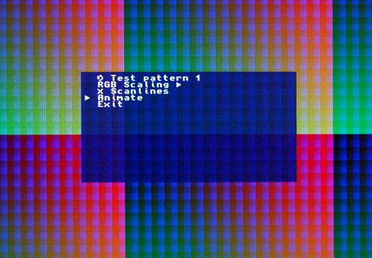
The first tag, called “StartingPoint” contains a VGA test pattern generator for the DE1 board, which has four slightly different test patterns selectable by the DE1’s switches.  In the coming parts I shall show how to eliminate the switches and replace them with an On Screen Display.
Continue reading

A closer look at the OSD/Control Module

Part 1 – an overview, and some details of the On-Screen Display

Both the OneChipMSX and PC Engine cores on this site make use the ZPUFlex processor to provide a bootstrap, control and OSD module.  Let’s take a closer look at this control module:

The control module needs to provide the following services:

  • Load a ROM from SD card (holding the host core off the SD card during the process, if necessary)
  • Provide an On-Screen Display, toggled by the F12 key.  The on-screen display must be generated in a form that can be merged with the host core’s video output.
  • Prevent keystrokes reaching the host core while the OSD is displayed
  • Allow various options to be set, and the settings to be read by the host core
  • Perform any high-level peripheral translation (keyboard-based gamepad emulation for the PC Engine core, mouse emulation for the OneChipMSX)

Continue reading

A new core…

NEC PC Engine!

Some months ago Gregory Estrade (AKA Torlus) created a PC Engine FPGA core which is available on GitHub – however his original version was targetted to the DE1 dev board, making use of the Flash memory and switches.  I’ve spent my very limited coding time over the last few weeks adding a control module, very similar to the one I added to the OneChipMSX core, and ported it to the Chameleon and MIST boards.

The project now has a page here.SHarrier

OneChipMSX Mouse support

I’ve been intrigued by SymbOS for a while, and being able to play with it was the main reason I wanted to try and port the CPCTrex core to a more current FPGA platform at some point (a task that will be tackled sometime between “one of these days” and “the heat death of the universe”, mainly because of the need for some kind of CompactFlash-to-SD bridge component.)  However, SymbOS runs on MSX as well (and could in theory be ported to anything Z80-based provided it has enough RAM), so now I have the OneChipMSX core at my fingertips, I can finally give SymbOS a whirl.

There was just one thing missing – a mouse!

Continue reading

Wiring up the Sega/CD32 adapter

A few weeks ago I pushed the PSoC Creator project for my Sega-6-button-to-CD32 converter project, but anyone wishing to build a converter would need to know the pin mapping.  This is defined within the Creator project, but figuring out which pins on the DB9s need to be wired to which terminals on the board would be pretty tedious – so here’s a wiring diagram for the benefit of anyone who wants to have a go.

(Please note, the board shown here is the CY8CKIT-049-42XX – the identical-looking 41XX won’t work because the chip lacks the programmable logic the project uses to create the shift register.)
Wiring