The Cyclone III board is housed at last!
3

Always worth a plug, 880 Gamer is a magazine produced in the style of the half-a-dozen or so glossy news-stand magazines we could choose from back in the Amiga’s heyday.
Distributed as a PDF, it also has two coverdisks in .adf format, and printable labels for each, should you wish to write them to physical disks!
All five issues of 880 gamer produced to date can be found at: http://www.users.on.net/~stanners/

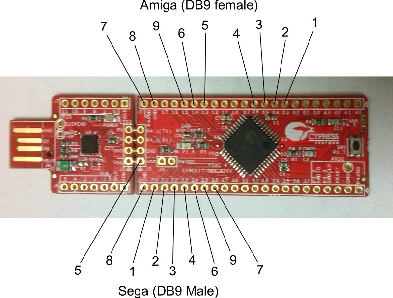
A few weeks ago I pushed the PSoC Creator project for my Sega-6-button-to-CD32 converter project, but anyone wishing to build a converter would need to know the pin mapping. This is defined within the Creator project, but figuring out which pins on the DB9s need to be wired to which terminals on the board would be pretty tedious – so here’s a wiring diagram for the benefit of anyone who wants to have a go.
(Please note, the board shown here is the CY8CKIT-049-42XX – the identical-looking 41XX won’t work because the chip lacks the programmable logic the project uses to create the shift register.)
Part 4: Up and running
I’m pleased to report that the first prototype of the PSOC4-based Sega 6-button pad to Amiga CD32 adapter is now up and running. In the process I’ve learned a lot about the PSOC4 platform, and I have to say as a development platform I really like it – I have no doubt I shall be using these devices in future projects.
PSOC Creator Project files for the adapter can be found at https://github.com/robinsonb5/SegaToCD32
Part 3: it lives!
I’ve finally got round to wiring up the prototype Sega 6-button to CD32 joypad adapter – here it is connected to an A500.
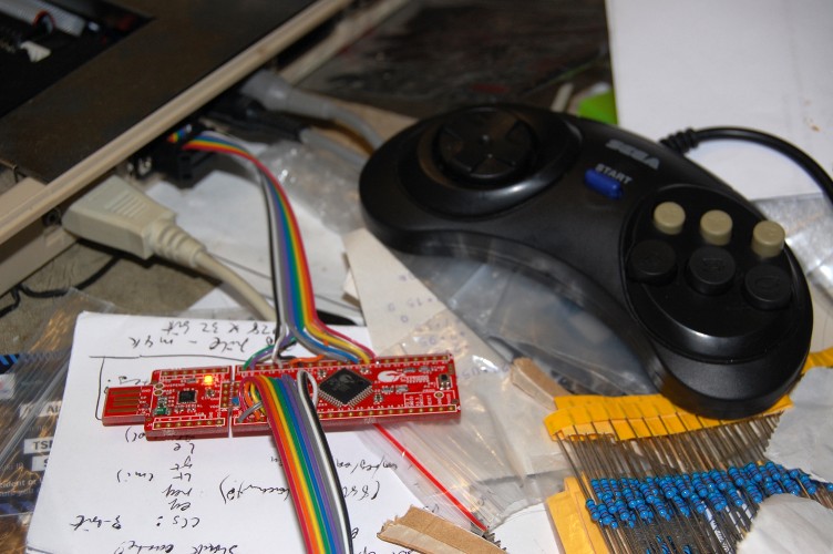
Does it work?
Well…. nearly! Directions and the first two fire buttons are fine, but the shift register still needs debugging.
Full project files for PSOC Creator can be found on GitHub: https://github.com/robinsonb5/SegaToCD32
Part 2: some code
In my earlier post I mentioned that I was going to handle reading the Sega 6-button joypad in software, using an interrupt routine, and use programmable logic to handle masquerading as a CD32 pad.
The six inputs from the Sega pad (up, down, left, right, button1, button2) are mapped to PSOC pins P2.0 to P2.5. Since these are adjacent, we can read and write to them easily as a single entity. We create a “pins” component with six inputs, named Sega_Inputs, and PSOC creator automatically generate headers and stubs so that we can read their status in main.c simply by calling Sega_Inputs_Read(). Similarly, we create an output pin, Sega_Select on pin P2.6, which we can write in the code using Sega_Select_Write().
Part 1: The Plan
One of the projects I have in mind for the PSOC4 chip on the CY8CKIT-049-42xx boards I picked up recently is an adapter to allow 6-button Sega Megadrive controllers to be used on the Amiga. I already made such a device a couple of years ago using a PIC microcontroller but never finished the project (I discovered FPGAs round about then!) and the programmable digital blocks in the PSOC4 make it an ideal platform for resurrecting the project.
Initially I shall read the Sega pad in software, using an interrupt routine, then implement the CD32-pad shift register using the programmable hardware in the PSOC4.
The original Sega Megadrive gamepad had four buttons: A, B, C and Start. The pad used a standard Atari-style 9-pin DSUB connector, and while the four directions and button B were mapped using standard Atari wiring (pins 1,2,3,4,6), button C appeared on pin 9. Most Atari-like gameport connectors have +5v available on pin 7, but the Sega variant has +5v on pin 5. Instead, pin 7 is used as a select signal, which multiplexes the pins normally occupied by the B and C buttons. When the select signal is high, B & C are readable, and when the select signal is low, the status of buttons A and Start appear on those lines instead.
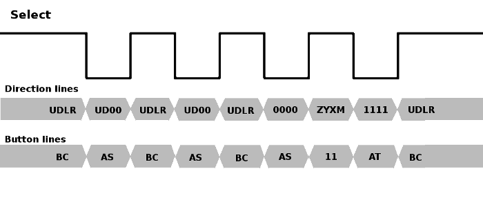
When it came to adding extra buttons to the six button pad, Sega needed to find a way of multiplexing extra buttons in such a way that they didn’t cause compatibility issues. The obvious solution of making extra buttons replace the direction lines when the select signal is low wasn’t possible because the existing 3-button protocol already held the left and right lines low when select was low, presumably so software could distinguish the 3-button pad from a standard Atari-style joystick or Master System controller. Instead they went with a “magic knock” approach, in which software toggles the select line four times in quick succession. The new buttons appear on the directions during the high pulse following the third low pulse, and to identify the pad as a six button button, the direction lines are low and high for the low pulses before and after this, respectively.
If you miss the days of there being half a dozen different Amiga magazines to choose from on the news-stands, then Mark Stanner’s on-line publication “880 Gamer” might make you smile! The PDF publication has a range of game reviews, a number of adverts from back in the day, reviews of a few scene demos, and even a letters page! If you miss the days of covermounted floppy disks, you won’t be disappointed, either, since there’s a cover disk in .adz format!
Issue 3 is out now, and can be found here: http://www.users.on.net/~stanners/

The circuit I cobbled together a few weeks ago to add sound support to the Gotek floppy emulator worked up to a point, but it was ugly as hell, and suffered from occasional stray oscillations. H.M. – the mastermind behind the new Amiga-compatible firmware for the Gotek unit – suggested using a MOSFET instead of the BJTs, and since I’m still shaky on the use of transistors it seemed like a good opportunity to learn.
There are various devices on the market which can emulate a floppy drive using disk images on a flash device of some kind. The best known of these is probably the HxC Floppy Emulator but there’s also a cheaper product, the Gotek floppy emulator.
Until recently the Gotek was no use with the Amiga, since it couldn’t cope with the Amiga’s unusual encoding scheme – all that changed a few weeks ago, however, when Hervé Messinger released a new firmware for the Gotek unit, written from scratch, which provides robust support for Amiga ADF images.
Needless to say, I couldn’t resist buying one of these to play with, and while the flashing process is a bit finicky, once it’s done the drive works well. I did find the complete silence from the drive a little disconcerting, however, so set out to modify the drive to provide some kind of audible feedback. Here’s the result:
I did this simply by wiring a couple of transistors to the “Step” signal on the floppy interface, which trigger a piezo sounder.
There are a couple of subtleties to take care of:
In my first attempt I placed the sounder between +12v and the collector of a transistor. This doesn’t work because a piezo sounder has a very high impedance and appears to the rest of the circuit like a small capacitor. Thus, when the transistor is activated, the sounder charges, but when the transistor deactivates the sounder is effectively open circuit, so nothing happens to the charge stored within. Instead, the transistor needs to be in parallel with the sounder, so that it discharges the charge stored in the sounder when activated, and allows fresh charge to build up when deactivated.
The other problem is that the step signal on the floppy interface is a very brief low pulse, with a specified minimum width of 1µs. In practice it’s quite a bit wider than that, but still very brief compared with the storage time of a typical bipolar junction transistor. What this means is that the transistor triggered by the Step pulse has to be a fast switching type with a very low storage time.