No, I haven’t vanished!

Apologies for the lack of recent updates.  I haven’t been completely idle but my time’s being filled with other things at the moment, including replacing light fittings, hanging pictures and learning the guitar!

Despite the silence, I’ve not been completely inactive on the FPGA front, however, and I’m still slowly building my library of demo projects for my “Flex” variant of the ZPU processor.  In the process I’m redesigning and streamlining a lot of the components that made up the TG68MiniSOC project, so that will be updated with the results before too much longer, and I’ve also started branching out from being purely Altera-based into Xilinx too.

This last development is the result of reader Emanuel Stiebler very generously supplying me with a Spartan-6 board!

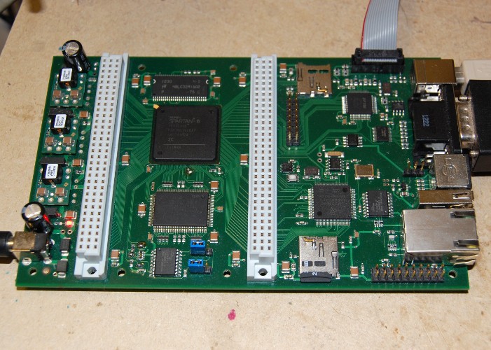
ESM-BB10

This has an XC6SLX45 FPGA, 32 megabytes of SDRAM, 4 megabyte of SSRAM, a microcontroller, dual micro-SD slots (one for the µC, one for the FPGA) and an assortment of IO ports.

I’ve already ported a few of the ZPU Demos to this new board (and a couple of the simpler ones to the original Minimig board while I’m at it!) but will post about the process in more detail soon.

Learn something new every day…

So while I’m experimenting with FPGA boards I generally upload a design into them at runtime via a USB-Blaster JTAG cable, and only rarely do I store a design permanently in a board’s configuration device.

Some of the boards I use have two separate connectors for the USB Blaster – one for direct programming of the FPGA and the other for Active Serial programming of an EPCS series flash device.  Others have an onboard microcontroller which handle configuration – and then there’s the Vampire 500 board.  This has a single JTAG connector and an EPCS4 configuration device, but no immediately obvious means of programming the EPCS4. Continue reading

Well that was nerve-wracking!

My Vampire500 board came with “some assembly required” – the FPGA, SDRAM and level translators were all in place, but installing the non-essential stuff – the micro SD slot and PS/2 socket – was left as an exercise for the user!

I want to press the Micro SD slot into service so that I can load alternative Kickstart ROMs, because my old A500 board has kickstart 1.3, and I need a more up-to-date ROM to test Zorro III autoconfig, and to run certain test software.

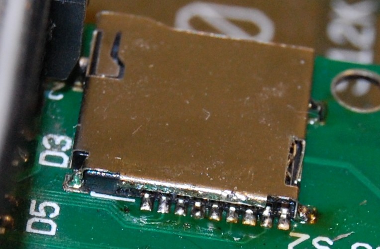
As it happens I haven’t done any surface mount work before, so I was a bit nervous about attacking an almost-one-of-a-kind board with a soldering iron – but after butchering the control board from a dead hard-drive and convincing myself that I *am* capable of soldering on that scale, I had a go at mounting the micro SD socket.  I was relieved to find that it has locating pegs that fit holes in the PCB, so at least I didn’t have to worry about alignment.

MicroSD

Well it *looks* OK – now to see if it actually works!